
rising pitch siren

The two-transistor siren circuit operates by utilizing the properties of transistors to create an oscillating signal that drives a loudspeaker. The basic components of the circuit include two NPN transistors, resistors, capacitors, and a loudspeaker.
In this configuration, the first transistor is connected in a feedback loop with the second transistor. The circuit is designed to charge and discharge a capacitor, which results in a changing frequency of oscillation. As the capacitor charges through a resistor, it eventually reaches a threshold voltage that turns on the second transistor. This action causes the first transistor to switch off, leading to a rapid discharge of the capacitor and a corresponding drop in voltage. This cycle repeats, creating an audible sound that increases in pitch over time.
To construct this circuit on a breadboard, the following steps should be followed:
1. Place the two NPN transistors on the breadboard. The collector of the first transistor should be connected to the base of the second transistor, while the emitter of the first transistor connects to ground.
2. Connect a resistor from the power supply (typically 9V) to the collector of the first transistor. This resistor limits the current flowing through the transistor.
3. Connect a capacitor between the collector of the first transistor and ground. This capacitor will charge and discharge, facilitating the oscillation.
4. Connect the loudspeaker in parallel with the capacitor to convert the oscillating signal into sound.
5. Ensure that all connections are secure and that the power supply is correctly connected to avoid damaging the components.
By adjusting the values of the resistors and capacitors, the frequency and pitch of the siren can be modified, allowing for experimentation and learning about electronic components and their behavior in a circuit. This circuit not only serves as a practical application of basic electronic principles but also provides an engaging project for beginners to enhance their understanding of oscillators and sound generation.A two transistor electronic siren breadboard circuit that produces an audible rising pitch on a loudspeaker. Tutorial and circuit for beginners in electronics.. 🔗 External reference
Related Circuits
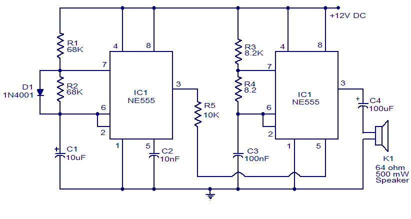
A variety of electronic circuits utilize the NE555 timer integrated circuit (IC). The circuit diagram presented illustrates a police siren based on two NE555 timer ICs, both configured as astable multivibrators. The circuit operates on a DC voltage supply...
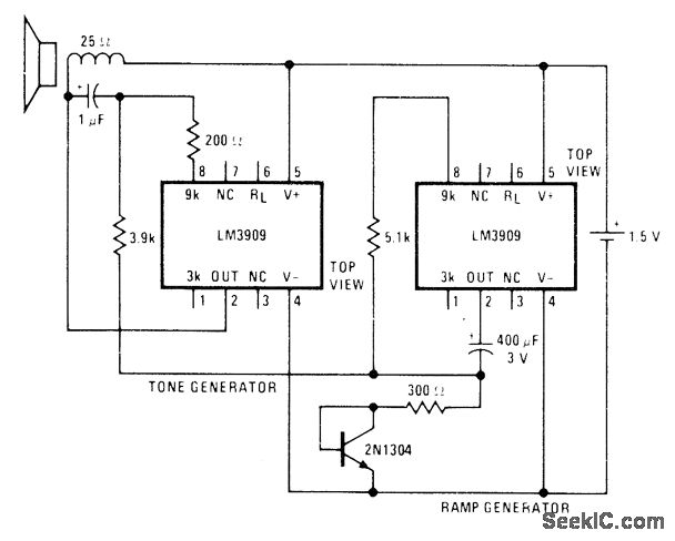
A low-drain circuit powered by a 1.5-V cell utilizes National LM3909 flasher integrated circuits (ICs) to replicate the "whooper" sounds characteristic of electronic sirens found in some city police cars and ambulances. Two flashers are necessary to create the...
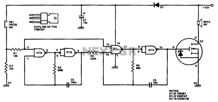
ICla and IClb are configured as a slow astable multivibrator, while IClc and ICld are arranged as a fast astable multivibrator. The output from the slow astable modulates the frequency of the fast astable, and the output from the...

The sound produced imitates the rise and fall of an American police siren. When first switched on, the 10 µF capacitor is discharged, and both transistors are off. When the push button switch is pressed, the 10 µF capacitor...

Two NAND gates are utilized in the oscillator configuration, while two additional NAND gates serve as control elements. To modify the two-tone speed, the 220 µF capacitors can be replaced with larger values for slower operation. For frequency adjustments...
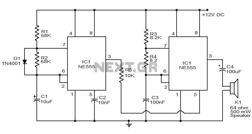
Numerous electronic circuits utilizing the NE555 timer IC have been published, and this is yet another example. The circuit diagram presented illustrates a police siren based on the NE555 timer IC. It employs two NE555 timer ICs, each configured...