
7400 Siren
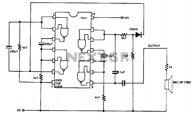
The circuit employs two NAND gates configured as an oscillator, which generates a square wave signal fundamental for producing audio tones. The oscillation frequency is primarily determined by the capacitors and the resistor in the timing network. In this configuration, the two NAND gates function as inverter stages, where the feedback loop formed by the resistors and capacitors dictates the oscillation frequency.
The use of 220 µF capacitors allows for a specific tone speed, which can be modified by substituting these capacitors with larger values. This adjustment results in a slower oscillation rate, effectively lowering the pitch of the generated tones. The capacitors of 0.2 µF and 0.1 µF are critical for fine-tuning the frequency; changing these components alters the charge and discharge times, thus affecting the output frequency of the oscillator.
R1 plays a vital role in the timing circuit; increasing its resistance will extend the oscillation period, thereby lowering the frequency. The 1.5 kΩ resistor is crucial for adjusting the frequency range between the two generated notes. By altering this resistor, the circuit can shift the pitch range, allowing for a broader spectrum of tones to be produced.
Overall, this oscillator circuit is a versatile design that can be easily modified by changing capacitor and resistor values, providing flexibility in sound synthesis applications.Two NAND gates are used for the oscillator, and two as the control. If the two-tone speed needs to be altered, the 220 µ capacitors can be changed Oarger for slower operation). If the frequency of the oscillator is to be changed, the 0.2 and 0.1 /iF capacitors can be varied and the value of Rl can be increased.
To change frequency range between the two notes, alter the 1.5 k (1,500) resistor= To change frequency range between the two notes, alter the 1.5 k (1,500) resistor. 🔗 External reference
Related Circuits
The sound produced imitates the rise and fall of an American police siren. When first switched on, the 10µF capacitor is discharged, and both transistors are off. When the push button switch is pressed, the 10µF capacitor will charge...

This circuit is designed for children's entertainment and is suitable for installation on bicycles, battery-powered cars, and motorcycles, as well as in models and other games. When switch SW1 is positioned as indicated in the circuit diagram, it reproduces...
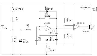
When the switch is pressed, capacitor C3 charges through resistor R4 with a time constant of 0.47 seconds. Upon releasing the switch, C3 discharges more slowly through resistors R7 and R3, with a time constant of approximately 5 seconds....
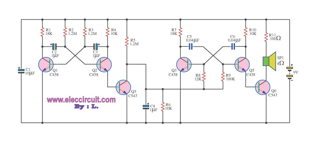
This circuit generates a sound similar to that of ambulance sirens. It differs from typical ambulance siren circuits in its design. The circuit utilizes a combination of oscillators and amplifiers to produce a sound that mimics the varying pitch and...
The circuit presented generates a smooth, piercing, wailing siren with minimal components. Additionally, three spare gates of the hex inverter IC1 are available, allowing the possibility of creating a cacophony by operating two sirens from the same integrated circuit....
The 555 timer on the right is configured as an alarm sound generator, while the second 555 timer on the left operates as a 1 Hz astable multivibrator. The output from the left timer modulates the frequency of the...