
Road remote control switch production

The wireless remote control switch circuit consists of several key components: the SH9902 receiver module, the 78L05 voltage regulator, and the relay for load switching. The SH9902 module is responsible for receiving signals from the remote control and decoding them to activate the relay. The 78L05 voltage regulator provides a stable 5V output necessary for the operation of the receiver module.
The circuit design includes a power supply section that converts the mains voltage to a lower DC voltage suitable for the receiver module. This section typically employs a transformer, rectifier, and filtering capacitors to ensure smooth operation. The connection of the negative pole to ground is critical for the proper functioning of the circuit.
The debugging process involves measuring specific voltage points throughout the circuit to ensure that each component is functioning correctly. The use of a multimeter is essential for verifying the output voltages at various IC pins, particularly during initial setup and troubleshooting.
Safety precautions are paramount when working with mains voltage. The recommendation to use an isolation transformer during debugging helps mitigate the risk of electric shock.
Once assembled and tested, the remote control switch can control various devices, such as lights or appliances, by sending signals through the remote control. The relay used in the circuit should be rated appropriately for the load it will control, and care should be taken to ensure that the circuit board is capable of handling the required current.
Overall, the wireless remote control switch circuit provides a convenient and practical solution for remote operation of electrical devices, with careful attention to design and safety ensuring reliable performance.This wireless remote control switch production is relatively simple. All components parameters we are testing is complete. Reader component parameters we provide installation can be completed in the production of the first resistive and capacitive components such as welding and welding on the IC socket Finally welding on the wireless receiver modu le SH9902. 78L05 first welding. Conditional netizens available external 5V DC power wireless receiving part debug plug IC1. Negative pole to the ground in the circuit. +5 V connected in 78L05 output of multimeter DC voltage range measuring IC1 14 feet voltage when pressing the remote control every time. 14 pin voltage should sometimes significantly change. Otherwise, the wireless receiver module is not working properly. receiver module with or without inserted upside as normal retest IC1 17 feet of the ground voltage hold the remote control.
feet voltage output is high or check IC1 whether the inserted upside Another point to be noted is that some production in soldering integrated circuit socket welding unskilled. address of 1-8 feet and the ground or high level collide. inadvertently decoder chip encoding. caused by the transmitter and receiver end address password is not uniform and can not be decoded on how to address coding.
below The article introduced; last measured 11. 12 feet voltage output high when the remote control button click the corresponding two feet. Mains supply part of the debugging: This part of the debugging circuit can be determined by measuring the value of the voltage as long as the voltage across the measurement CW1 If the measured voltage is 11 13V between the section and the rectifier of the capacitor buck part of the circuit is working. So users can quickly master this remote switch debugging techniques. Especially in the production of a good circuit board drew three red circle. Specific location is shown in Figure 3. Measuring four-point voltage can judge whether the circuit working. this four-point voltage: +12 V voltage is the +5 V voltage. radio received signal demodulated voltage and the data is successfully decoded voltage the several voltage test point in the position of the circuit board is shown in Figure 3, three red circle.
four-point test points SC2272 17 feet when decoding success this foot will output a high output low on the contrary. circuit mains powered directly. production to pay special attention to safety when all lines The conductive portion of the board not to touch it.
Otherwise, electric shock accident prone. best able to do so through a 1:1 isolation transformer for debugging. After more than commissioning work. Items are normal. Piece of circuit board mounted in the housing. Then loaded onto the fixing screws a remote switch finished next test machine 220V mains in Figure marked with the words AC terminals respectively connected to the two leads of the two bulbs labeled L1 ³ L2 ³ terminals of the word power by two switches. corresponding lit two lights Off. switch off lamps lit. 10A capacity relay control switch used. Thinner circuit board copper can not get through the 10A current control load power greater than 100W.
Switch line copper coupled with solder. deflector Another point which should be noted that when the load power of the switch is large. there may not immediately open lamp lights when the remote control switch when the large current due to load interference due to decoding approach: the capacitance set product uses the remote control at the switch and then a 0. 47uF/400V launch a distance of 200 meters in the actual use of the influence of environmental factors.
distances become nearly many. use the best distance control in less than 10 m. However, for the average household, then the distance is completely meet the requirements. 🔗 External reference
Related Circuits
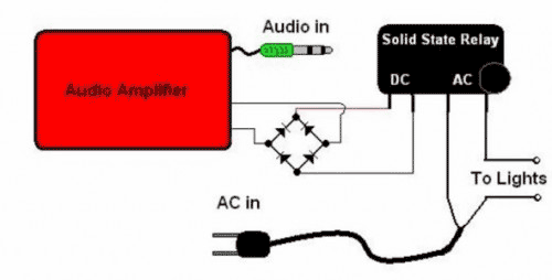
The basic Idea was to have Christmas lights flash with the music. In my design I use an ordinary amplified computer speaker, a diode bridge, and a ‘CRYDOM’ SSR (Solid State Relay). In order to increase the time that...
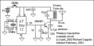
This section describes an experimental low power, low bandwidth data signaling system that was initially made to operate at 55 MHz (television channel 2 in the U.S.). Before operating a radio transmitter, find out what kind of transmitter operation,...
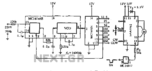
A typical application example is presented, demonstrating the SAA1042 12V stepper motor drive configuration. The phase winding current is set at 200mA. According to RB Figure 5-10, a resistor value of RE = 56kΩ is selected. This resistor is...

A simple 16-volt switching power supply circuit can be constructed using the provided diagram, which is based on the MAX668 constant-frequency, pulse-width modulating (PWM), current-mode DC-DC controller. This integrated circuit is designed for a wide range of DC-DC conversion...
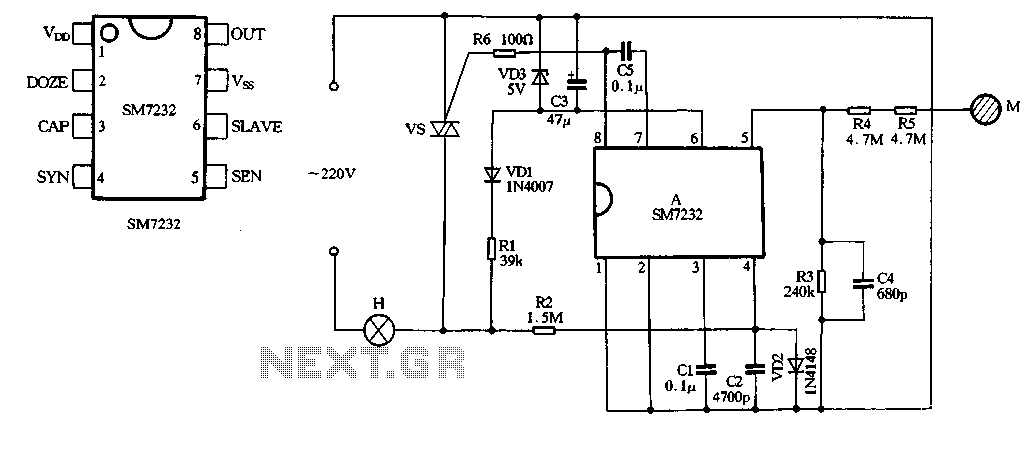
The core component of the circuit is the dimmer, utilizing the SM7232 integrated circuit. The pin configuration includes: 1) VDD, the positive power supply terminal; 2) DOZE; 3) CAP; 4) SYN, which synchronizes input power frequency using an internal...
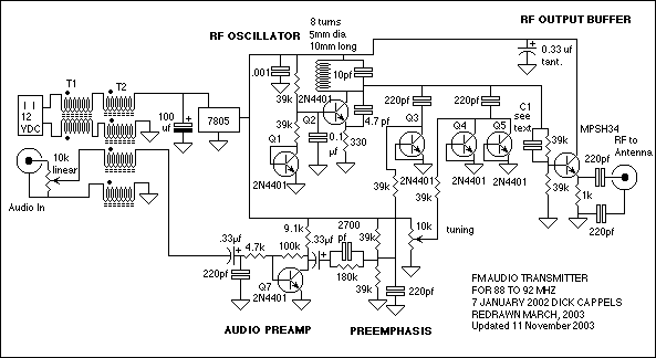
The circuit consists of a frequency modulated oscillator, an audio preamplifier with pre-emphasis to supply the frequency modulating signal, and a buffer amplifier to drive the antenna connector. Oscillator's frequency is determined by L1 resonating with the 10 pF...