
5 zone alarm circuit
This alarm system is designed for reliability and ease of use in residential or small commercial applications. The integration of three CM ICs simplifies the circuit design while maintaining functionality across multiple zones. The use of normally closed contacts enhances security by ensuring that any disruption to the circuit will activate the alarm. The timed entry/exit feature allows users to enter or exit the premises without triggering the alarm, which is crucial for practical operation.
The circuit's design includes various components to enhance its performance. The input capacitors, C1-C5, not only provide RF immunity but also help to filter out potential noise that could interfere with the alarm's operation. The transient suppressor formed by C7 and R14 protects the circuit from voltage spikes that could occur during power fluctuations, ensuring longevity and reliability of the system.
The key switch serves as a critical control point for the system, allowing users to set or unset the alarm as needed. The choice of a metal key switch is advisable for added security, preventing unauthorized access to the system's controls. The exit delay, governed by the charging of C6 through R11, provides a user-friendly feature that allows for a brief window to exit the premises after setting the alarm.
The LED indicators serve as a visual confirmation of the system's status, enhancing user experience and ensuring that users are aware of the system's armed state. The concealed re-entry switch is a clever addition, allowing users to enter the building without triggering the alarm, which is especially useful in scenarios where quick access is needed.
Overall, this alarm system is a robust solution for securing small spaces, providing essential features that address both functionality and user convenience. The combination of independent zones, visual indicators, and thoughtful design elements results in a comprehensive security system that can be easily installed and operated in various environments.This is a complete alarm system with 5 independent zones suitable for a small office or home environment. It uses just 3 CM IC`s and features a timed entry / exit zone, 4 immediate zones and a panic button. There are indicators for each zone a system armed indicator. The schematic is as follows: Each zone uses a normally closed contact. These c an be micro switches or standard alarm contacts (usually reed switches). Suitable switches can be bought from alarm shops and concealed in door frames, or window ledges. Zone 1 is a timed zone which must be used as the entry and exit point of the building. Zones 2 5 are immediate zones, which will trigger the alarm with no delay. Some RF immunity is provided for long wiring runs by the input capacitors, C1-C5. C7 and R14 also form a transient suppresser. The key switch acts as the Set/Unset and Reset switch. For good security this should be the metal type with a key. At switch on, C6 will charge via R11, this acts as the exit delay and is set to around 30 seconds. This can be altered by varying either C6 or R11. Once the timing period has elapsed, LED6 will light, meaning the system is armed. LED6 may be mounted externally (at the bell box for example) and provides visual indication that the system has set. Once set any contact that opens will trigger the alarm, including Zone 1. To prevent triggering the alarm on entry to the building, the concealed re-entry switch must be operated.
This will discharge C6 and start the entry timer. The re-entry switch could be a concealed reed switch, located anywhere in a door frame, but invisible to the eye. The panic switch, when pressed, will trigger the alarm when set. Relay contacts RLA1 provide the latch, RLA2 operate the siren or buzzer. 🔗 External reference
Related Circuits
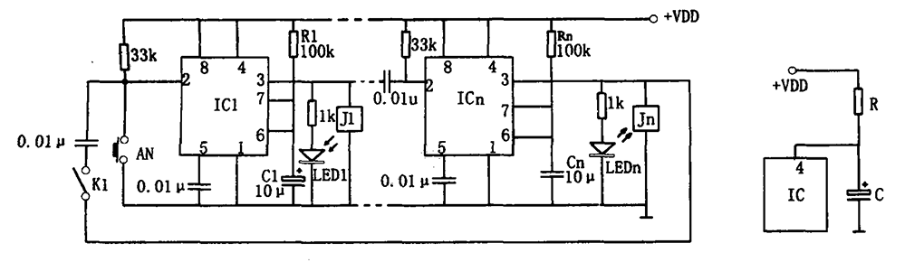
The multi-channel temperature measurement circuit is illustrated in the figure. The core of the test circuit comprises a 555 one-shot delay circuit. When the button is pressed, the output pin of the 555 timer (IC1) goes high due to...
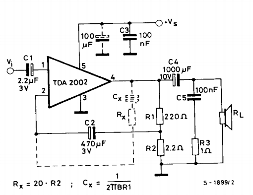
This is a power amplifier circuit built using the TDA2002 power amplifier IC module. It serves as a replacement for the original LM383, which is no longer available. The circuit is easy to assemble and requires a minimal number...
The standard assumption is that the phase shift sections operate independently. According to the equation provided, the loop phase shift reaches -180 degrees when the phase shift of each section is 60 degrees. This condition is met when ω...
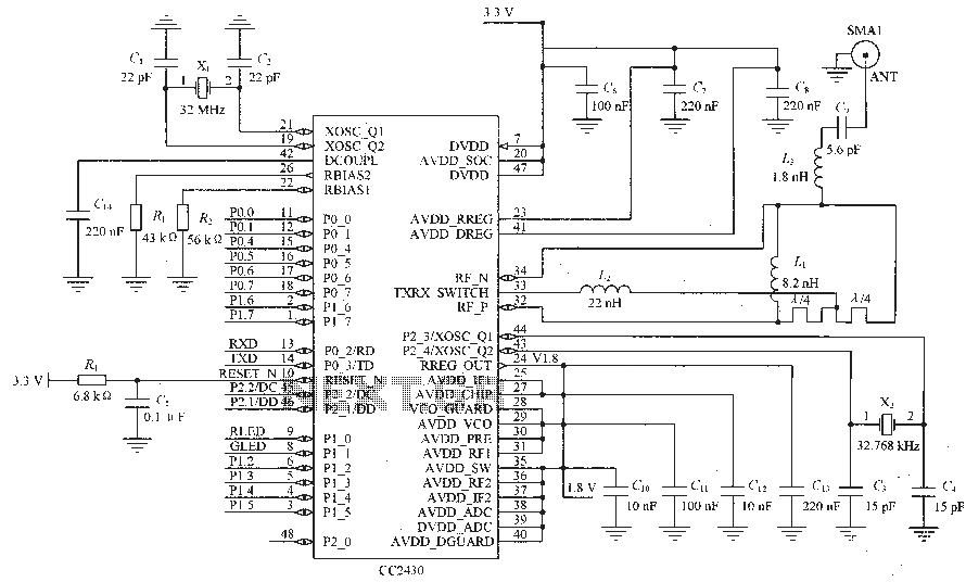
Figure C1 and C2 depict a 22 pF capacitor connected to a 32 MHz crystal oscillator circuit, which utilizes a quartz crystal for standard operation. Capacitors C3 and C4, each rated at 15 pF, are connected to a 32.768...
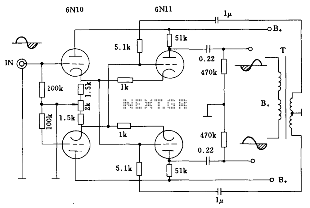
Balanced cross tube inverter circuit, also known as the Chelles inverter circuit, can be utilized as a preamplifier and employs 6N10 and 611 tubes in an inverted configuration. The circuit is designed to work with a final amplifier tube, specifically...
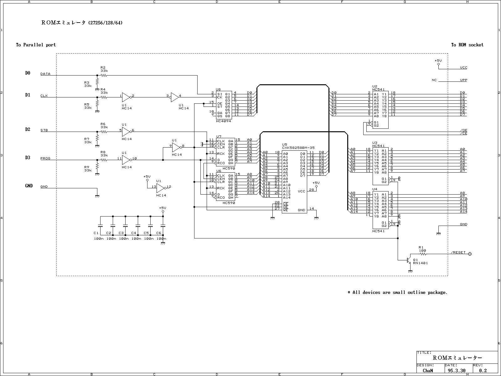
This ROM emulator improves the easiness to build/use it by reducing down its function which can be used as a ROM emulator. The kind of the ROM types to be emulated are 2764, 27128, and 27256. The debugging capability...
Warning: include(partials/cookie-banner.php): Failed to open stream: Permission denied in /var/www/html/nextgr/view-circuit.php on line 713
Warning: include(): Failed opening 'partials/cookie-banner.php' for inclusion (include_path='.:/usr/share/php') in /var/www/html/nextgr/view-circuit.php on line 713