
robotic vacuum cleaner
The robotic vacuum circuit design integrates several key components to achieve its operational goals. The heart of the system is the Mega32 microcontroller, which acts as the central processing unit. This microcontroller is responsible for interpreting the data received from the accelerometer and generating commands for the motors based on the robot's movement and obstacle detection.
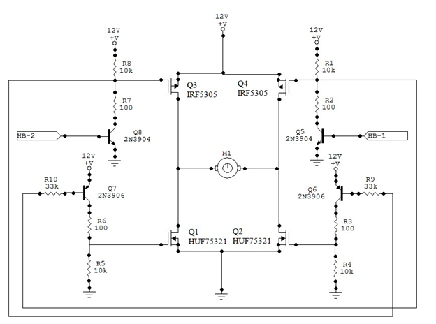
The accelerometer, connected to the Mega32, provides real-time feedback on the robot's orientation and movement. Its outputs are processed through the microcontroller's analog-to-digital converter, allowing for precise calculations regarding the robot's position relative to obstacles. The stepper motors, which drive the robot's movement, are controlled via the microcontroller's digital output pins. These motors allow for accurate positioning and movement control, enabling the robot to navigate its environment effectively.
The DC motor is employed to power the rotating brush underneath the robot, enhancing its vacuuming capability. The motor's speed and operation can be adjusted through the microcontroller, allowing for optimal performance based on the surface being cleaned.
Power management is facilitated by the 9V battery, which supplies energy to the entire system. The battery clip's 3V output is specifically utilized to power the accelerometer, ensuring that all components function harmoniously without power fluctuations that could affect performance.
Overall, this robotic vacuum design emphasizes simplicity and cost-effectiveness while incorporating essential features for autonomous operation. The combination of stepper motors for mobility, an accelerometer for collision detection, and a motorized brush for cleaning creates a functional prototype that adheres to the project's budgetary constraints and operational goals.We decided to design and build a robot capable of vacuuming the floor of a room or area without any human interaction other than just starting the unit. We realized the need for a cheap and convenient product that can be easily used to vacuum a room on its own, saving a person valuable time.
The robotic vacuum is mainly built from a circular piece of foam board, as shown in Figure 1. The robotic vacuum uses a rotating brush underneath the unit to vacuum a carpet as it passes over it, as shown in Figure 2. Two stepper motors, aligned across the center axis of the robot, are used to accurately drive the robotic vacuum around a room.
Because the body of the robot is circular and the steppers are placed along the center axis, the robot can spin in place in any direction. One free-spinning chair wheel is located at the rear of the robot to keep it balanced. The robot is programmed to sense the direction of a collision with an obstacle using an onboard accelerometer.
If the robotic vacuum hits an object head-on, it backs up and changes direction. If an obstacle is hit at an off-angle, the robotic vacuum turns away from the direction of the impact. The robotic vacuum`s movement is based upon a random walk around a room, which theoretically will cover the entire area of a room given enough time.
The robot is programmed to drive straight until an obstacle is hit. At that point, it will turn and continue driving straight until another obstacle is hit, and so on. Our project was inspired by an existing robotic vacuum cleaner, the Roomba ®. Current robotic vacuum cleaners on the market, produced by iRobot and Electrolux, can cost up to $1700. The idea of a designing and building a device that can perform the same functions as the existing market brands on a budget of $50 was a challenge that we wanted to take on.
We had an idea of the supplies and equipment available to us and realized that our robot could be built using an accelerometer, several motors and a microcontroller, among various other pieces of equipment. We considered obstacle avoidance, but realized that IR sensors would be too expensive to implement and would not be necessary.
A slight collision with an obstacle could be detected by our accelerometer, and the appropriate response could be programmed with our microcontroller. Because we are using stepper motors for our bot, it is theoretically possible to determine the distance traveled by each wheel and perform room size calculations, which could have been inputted to an algorithm to better cover the room.
However, we discovered a torque problem when we realized that the wheels sometimes slip on the carpet surface, and other times do not move at all. Because of the torque inconsistencies, proper distance determination would not have been possible, so our only option for covering an entire room was to use a random walk in which the robotic vacuum collides with an obstacle and heads off in a different direction until the room is vacuumed.
Initially, this bot was designed with only a carpet-sweeping function in mind. A carpet sweeper, which picks up trash as it is swept across the floor, is not a motorized device. If the carpet sweeper did not satisfactorily pick up trash off the floor, we would motorize it to spin using a DC motor. After some testing, we decided to motorize the sweeper for other reasons. The 9V battery clip can hold one 9V battery. The clip contains a 3V output, which is connected to the accelerometer`s Vcc connection. The Mega32 MCU is directly connected to the battery on the battery clip. The signal from the accelerometer is inputted into the MCU`s analog to digital converter. The x-axis output is sent into port A0, and the y-axis output is sent into port A1 on the Mega32. After several calculations are made, the MCU sends the appropriate commands to the stepper motors and DC motor.
The stepper motors and DC motor are conne 🔗 External reference
Related Circuits
An ultrasonic cleaner is effective for cleaning specific items. This circuit employs a microcontroller to manage timing and provide a digital display, although a basic oscillator can be utilized if preferred. RESL and RES2 are piezoelectric transducers activated by...
The circuit operates using AC mains voltage and other high voltages that pose risks of injury or death. The 125 employs a basic heterodyne configuration, where the outputs of two similar radio-frequency Colpitts oscillators are fed into a mixer,...
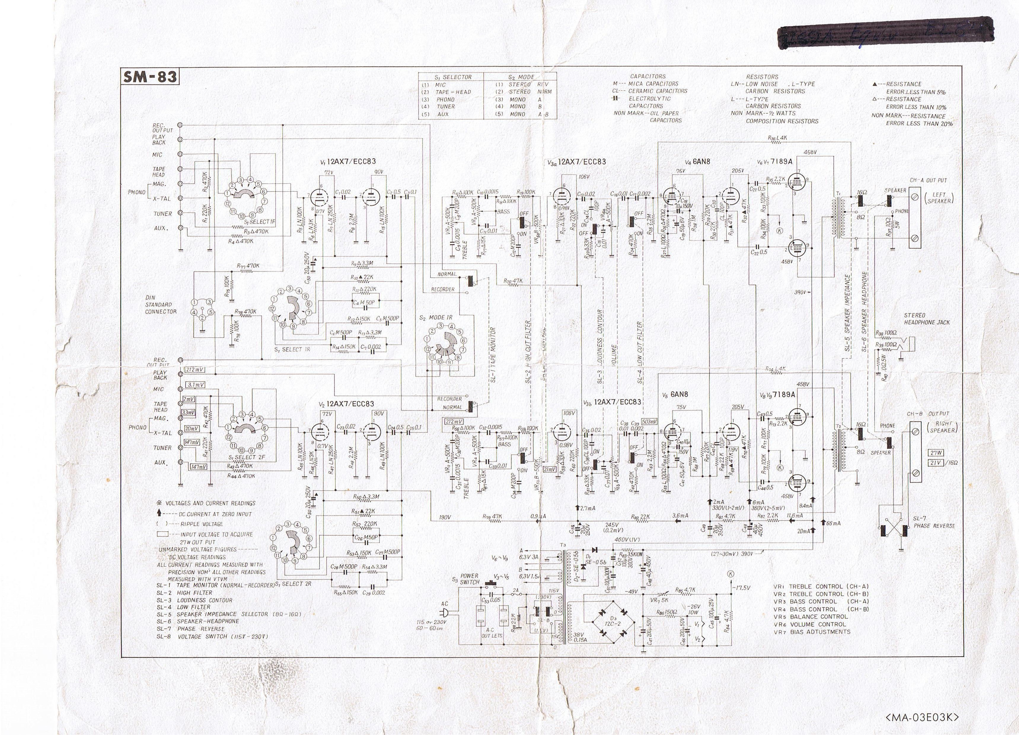
Where can one obtain a 12AX7 tube? These tubes are very popular for use in the preamplifier stages of many professional electric guitar amplifiers. A good music store will have them available for a modest price (around $12 US...
The TINAH board shield is a printed circuit board designed for the Phys253 course, first utilized in 2009 by Engineering Physics students and faculty. This shield functions as a buffer to protect the digital and analog inputs and outputs...
After restoring a Fisher 400, the search for another tube amplifier began, motivated by a desire to apply newly acquired skills. Importing equipment from the USA to the European Union proved costly, with shipping fees around $200 to $250,...
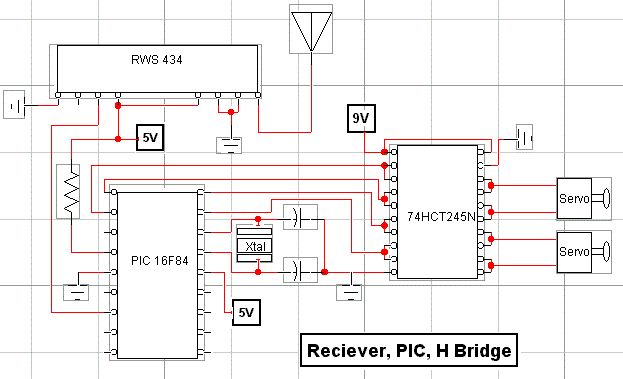
RF technology is an exciting field to incorporate into electronic designs. However, for beginners, constructing reliable RF transmitters and receivers can be challenging. RF (Radio Frequency) technology plays a crucial role in modern communication systems, enabling wireless data transmission over...