
Engineering Physics Block-Stacking Robotics Project (2012)
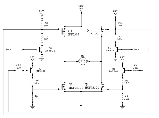
The TINAH board shield is an advanced integration of various sensor technologies and motor control systems designed to enhance robotic functionality in educational settings. The use of QRD 1114 reflectance sensors allows for precise tracking of black tape, which is essential for navigation in robotics applications. The incorporation of H-Bridge motor drivers is critical, as these circuits enable the efficient management of motor control through PWM, allowing for smooth acceleration and deceleration of the robot while maintaining high power output. The selection of 25A MOSFETs in the H-Bridge design is a strategic choice to handle the high currents required for driving motors effectively, ensuring that the robot can perform demanding tasks without risking damage to the components.
The design also addresses potential interference issues that could affect sensor performance. By enclosing the QRD sensors in a protective housing, the design minimizes the impact of ambient light and other disruptive signals, thereby improving the accuracy of the tape-tracking algorithm. This consideration is vital in environments where lighting conditions can vary significantly.
The choice of power source is another crucial aspect of the TINAH board's design. The decision to use NiMH batteries over LiPo batteries was based on the need for stable current delivery without the risk of damaging fuses during operation. This highlights the importance of selecting appropriate components and power sources in ensuring the reliability and longevity of robotic systems.
Overall, the TINAH board shield represents a comprehensive approach to robotic design, integrating multiple sensors, motor control strategies, and power management techniques to create a robust platform for educational and experimental purposes in the field of engineering physics.The TINAH board shield, a printed circuit-board shield designed and built for Phys253 and first used in 2009 by Engineering Physics students and staff. The shield acts as a buffer for protecting the digital and analog inputs and outputs of the Wiring board, and allowing for built-in functions.
- Six analog inputs were used for QRD 1114 refle ctance sensors, with five of them being used for the robot`s ability to track the black tape. Five digital inputs were used for mechanical switches, for use in collision detection. Due to the TINAH board`s limited ability to provide current to attached devices, three motor-driver circuits were built to allow the TINAH to control the motor speeds and directions using Pulse-Width Modulation (PWM), while having the current provided by the battery source. These circuits, known as H-Bridges are comprised of high-current elements that allowed the motors to be driven at much higher powers than would be possible by using PWM outputs from the TINAH alone.
By using 25A MOSFETs, the circuit shown below proved to be robust enough for the reliable operation of the robot. This sensor acts as a robotic eye that produces infrared (IR) light, and varies its conductivity depending on the amount of infrared light that is reflected back to the phototransistor.
Due to this, it is optimal in detecting the difference in the amount of reflected light between an object that is dark (black tape) and light (white wood). Unfortunately, this sensor is also very susceptible to interference from everything from natural light, 60 Hz (utility frequency) artificial sources and IR rangefinders on cameras.
Due to this, the team created a housing to shield the sensors from these sources, to ensure the reliability of the tape-tracking algorithm. The batteries used were Nickel Metal Hydride (NiMH) cells at 16V. Although Lithium Polymer (LiPo) batteries were provided, the team found that the low internal resistance of the LiPo batteries, and the uneven switching time of the MOSFETs in the H-bridge circuits caused major current spikes, destroying several 10A fuses during the operation of the robot.
The tape-tracking inputs consisted of five QRD sensors to detect the black tape along the playing surface. Two main QRD sensors, placed at a distance from each other equalling the width of the tape on the bottom of the chassis act to steer the robot along straight portions of the tape.
In addition, two more sensors at a larger width and mounted in front of the initial tape-tracking sensors act as feed-forward sensors for determining turn direction. The last sensor, mounted on the side of the chassis, acts to align the robot with certain tape lines to ensure accurate placement and stacking of the blocks.
To detect the levels which the belt-driven arm would move to, the team used a single shielded QRD sensor attached to the arm, along with a stationary strip with several black lines to act as an encoder for the system. This situation eliminated the four mechanical micro-switches, and used a similar implementation to the tape-tracking inputs as detailed above.
🔗 External reference
Related Circuits
The following circuit illustrates a Tachometer Circuit Project. This circuit is constructed using the 555 Timer IC. Features include a monostable IC and voltage capabilities. The Tachometer Circuit utilizes a 555 Timer configured in monostable mode to measure the rotational...

What is the likely cost of the Aleph Ono, specifically regarding the parts? Is it similar to the Pearl but improved? The Aleph Ono is a high-fidelity phono stage designed to deliver exceptional audio performance. When estimating the cost of...
This simple wind charger circuit project is designed using the LTC1042 monolithic CMOS window comparator, manufactured by Linear Technology. The wind charger circuit utilizes wind power to generate the energy necessary for charging Ni-Cd or lead-acid batteries. When the...
This is the initial phase of an Arduino-controlled PWM RGB LED project, which incorporates distance and PIR sensor control along with a sleep mode feature. The project utilizes an Arduino microcontroller to manage a Pulse Width Modulation (PWM) RGB LED,...
This is one of the most basic 555 circuits. This circuit is part of the chip's datasheet, complete with the math needed to design to specification, and is one of the reasons a 555 is referred to as a...
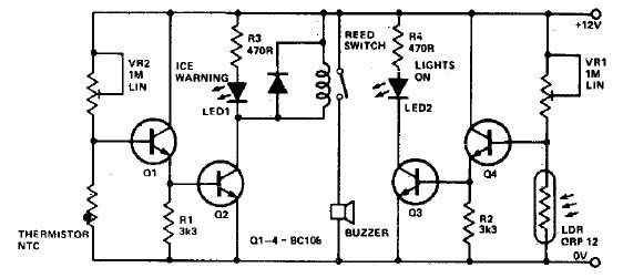
This electronic project circuit diagram for an ice warning and lights reminder system alerts drivers when their vehicle lights should be activated and warns them if the outside temperature approaches zero degrees Celsius. The system employs an LED indicator...