
Ultrasonic Cleaner Circuit
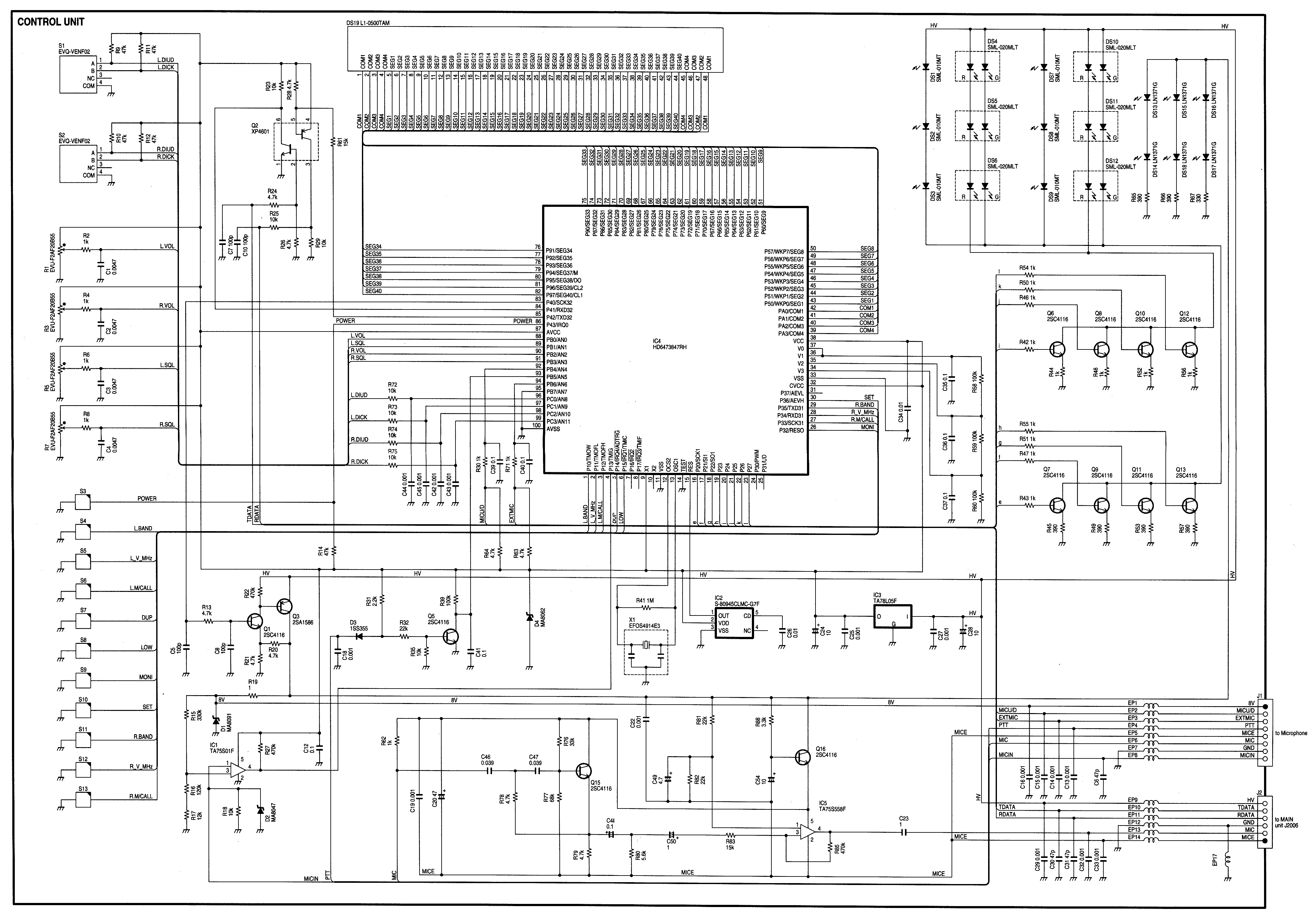
The ultrasonic cleaner circuit is designed to facilitate the removal of contaminants from delicate items using high-frequency sound waves. The core components of the circuit include a microcontroller, piezoelectric transducers, a power oscillator, and a rectification stage.
The microcontroller serves as the central control unit, managing the timing of the ultrasonic cleaning cycles and providing a digital readout of the operational status. It can be programmed to set various cleaning durations, allowing users to customize the cleaning process according to the specific requirements of the items being cleaned.
The power oscillator, designated as Q1 in the circuit, generates the ultrasonic frequency necessary for effective cleaning. Operating within the range of 40 to 60 kHz, this frequency is optimal for creating cavitation bubbles in the cleaning solution. These bubbles implode upon contact with the surfaces of the items, dislodging dirt and contaminants without causing damage.
The piezoelectric transducers, RESL and RES2, convert the electrical signals from the power oscillator into mechanical vibrations. These vibrations propagate through the cleaning solution, creating the ultrasonic waves that facilitate the cleaning process. The arrangement and positioning of these transducers are critical for achieving uniform ultrasonic coverage within the cleaning tank.
The bridge rectifier-capacitor input filter converts the AC line voltage into a suitable DC voltage for powering the oscillator. This stage ensures that the circuit operates efficiently and reliably, providing a stable power supply to the oscillator and transducers.
Overall, this ultrasonic cleaner circuit is a sophisticated yet practical solution for efficiently cleaning delicate items, leveraging the principles of ultrasonic technology to achieve superior cleaning results. Ail ultrasonic cleaner is useful to clean certain items. This circuit uses a microcontroller to control timing and give a digital readout, but only the basic oscillator can be used, if desired. RESL, RES2 are piezoelectric transducers driven by power oscillator Ql. Ql is powered by a bridge rectifier-capacitor input filler that operates directly off the ac line. The frequency is 40 to 60 kHz. 🔗 External reference
Related Circuits
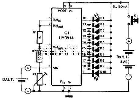
The LM3914A bar graph LED is utilized as a voltmeter for testing batteries. This circuit operates on a 4.5-V battery and compares the battery under test with an internally generated reference, established by resistors R1, R2, and potentiometer P1....
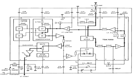
The TDA7000 is an integrated circuit (IC) designed for FM portable radios, featuring a Frequency-Locked Loop (FLL) system with an intermediate frequency of 70 kHz. It incorporates several functions, including an RF input stage, mixer, local oscillator, IF demodulator,...
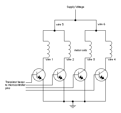
When moving objects with microcontrollers, three types of motors are particularly useful: DC motors, servomotors, and stepper motors. Most motors operate on the electrical principle of induction. When electric current flows through a wire, it generates a magnetic field...
Radio Control Circuits PDF Manual Download. This document serves as a comprehensive guide to radio control circuits, intended for individuals seeking to understand the principles and applications of radio frequency (RF) technology in controlling various devices. The manual covers fundamental...
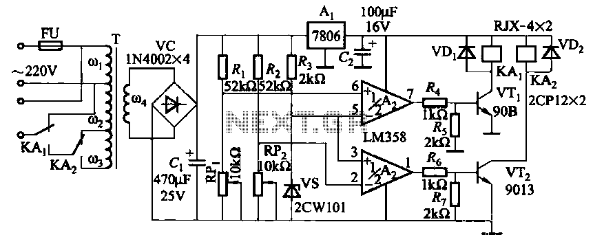
It utilizes two LM358 operational amplifiers, A2 and Ar, to create a voltage measurement comparison control circuit for upper and lower limit voltage settings. The circuit includes a Raspberry Pi adjustment potentiometer (RPi) and an additional potentiometer (RP2) to...
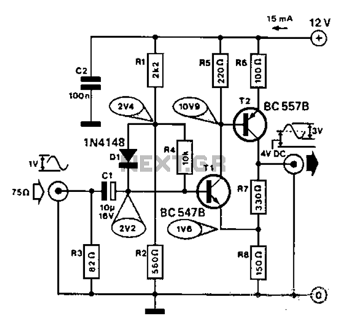
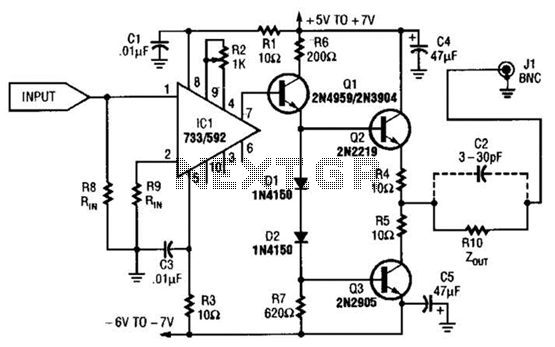
Commonly used for cameras or computers with black and white television connections, the amplifier has a gain of 3 and a bandwidth of 10 MHz. The described circuit is an amplifier designed for applications involving cameras or computers that interface...