
Rectifier/filter circuit Semiconductors
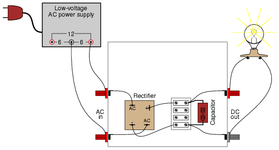
The bridge rectifier serves as a crucial component in converting alternating current (AC) to direct current (DC). This conversion is essential for powering various electronic devices and circuits that require a stable DC voltage. The design of the rectifier circuit typically involves four diodes arranged in a bridge configuration, allowing for full-wave rectification. The inclusion of a filter capacitor smooths out the pulsating DC output, ensuring a more stable voltage level for downstream applications.
When selecting components for the bridge rectifier, it is essential to consider the maximum load current and voltage ratings. The rectifier's specifications should match or exceed the expected operational parameters to ensure reliability and prevent component failure. Additionally, proper heat dissipation strategies, such as using a metal enclosure and ensuring adequate airflow, should be implemented to maintain optimal operating temperatures.
In summary, the construction of a bridge rectifier circuit with a metal enclosure and appropriate component selection is vital for achieving an efficient and reliable power supply solution. This setup not only enhances performance but also ensures the longevity and maintainability of the circuit.A bridge rectifier "pack" is highly recommended over constructing a bridge rectifier circuit from individual diodes, because such "packs" are made to bolt onto a metal heat sink. A metal box is recommended over a plastic box for its ability to function as a heat sink for the rectifier.
A larger capacitor value is fine to use in this experiment, so long as its working voltage is high enough. To be safe, choose a capacitor with a working voltage rating at least twice the RMS AC voltage output of the low-voltage AC power supply. High-wattage 12-volt lamps may be purchased from recreational vehicle (RV) and boating supply stores.
Common sizes are 25 watt and 50 watt. This lamp will be used as a "heavy" load for the power supply. This experiment involves constructing a rectifier and filter circuit for attachment to the low-voltage AC power supply constructed earlier. With this device, you will have a source of low-voltage, DC power suitable as a replacement for a battery in battery-powered experiments.
If you would like to make this device its own, self-contained 120VAC/DC power supply, you may add all the componentry of the low-voltage AC supply to the "AC in" side of this circuit: a transformer, power cord, and plug. Even if you don`t choose to do this, I recommend using a metal box larger than necessary to provide room for additional voltage regulation circuitry you might choose to add to this project later.
The bridge rectifier unit should be rated for a current at least as high as the transformer`s secondary winding is rated for, and for a voltage at least twice as high as the RMS voltage of the transformer`s output (this allows for peak voltage, plus an additional safety margin). The Radio Shack rectifier specified in the parts list is rated for 25 amps and 50 volts, more than enough for the output of the low-voltage AC power supply specified in the AC experiments chapter.
Rectifier units of this size are often equipped with "quick-disconnect" terminals. Complementary "quick-disconnect" lugs are sold that crimp onto the bare ends of wire. This is the preferred method of terminal connection. You may solder wires directly to the lugs of the rectifier, but I recommend against direct soldering to any semiconductor component for two reasons: possible heat damage during soldering, and difficulty of replacing the component in the event of failure. Semiconductor devices are more prone to failure than most of the components covered in these experiments thus far, and so if you have any intent of making a circuit permanent, you should build it to be maintained.
"Maintainable construction" involves, among other things, making all delicate components replaceable. It also means making "test points" accessible to meter probes throughout the circuit, so that troubleshooting may be executed with a minimum of inconvenience.
Terminal strips inherently provide test points for taking voltage measurements, and they also allow for easy disconnection of wires without sacrificing connection durability. Bolt the rectifier unit to the inside of the metal box. The box`s surface area will act as a radiator, keeping the rectifier unit cool as it passes high currents.
Any metal radiator surface designed to lower the operating temperature of an electronic component is called a heat sink. Semiconductor devices in general are prone to damage from overheating, so providing a path for heat transfer from the device(s) to the ambient air is very important when the circuit in question may handle large amounts of power.
A capacitor is included in the circuit to act as a filter to reduce ripple voltage. Make sure that you connect the capacitor properly across the DC output terminals of the rectifier, so that the polarities match. Being an electrolytic capacitor, it is sensitive to damage by polarity reversal. In this circuit especially, where the internal resistance of the transformer and rectifier are 🔗 External reference
Related Circuits
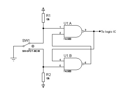
In most digital electronics projects that utilize various types of switches, switch bounces are frequently encountered. These are additional glitches that occur following the actual operation of the switch. These small pulses can disrupt the proper functioning of the...
The stroboscope tube requires approximately 250-400V DC for operation. This high voltage is generated by a simple voltage step-up circuit constructed from transistors Q1, Q2, and transformer T1. This circuit outputs about 230V AC, which is then rectified by...
The only drawback of a single operational amplifier (op-amp) stage is that it inverts the signal, necessitating an additional inverting buffer to restore the original phase if absolute phase is a concern. Various schematics exist for both configurations, but...
Chevy S-10 Blazer Ignition Control (IC) Circuit Wiring Diagram. The Chevy S-10 Blazer ignition control circuit is a critical component in the vehicle's ignition system, responsible for managing the timing and operation of the engine's spark plugs. The circuit typically...
Each time switch S1 is closed the count on the CD4017 advances by 1 step and the corresponding LED turns on. When the maximum count plus 1 is reached for each circuit the cycle is restarted and repeats. The circuit...
A DIY GSM jammer schematic diagram designed for use with GSM1900, operating within the frequency range of 1930 MHz to 1990 MHz. The GSM jammer circuit is intended to disrupt communication between mobile phones and base stations within the specified...