
Rock Face effect for guitars
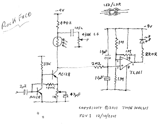
The described circuit is an enhancement of the traditional Fuzz Face design, incorporating optical temperature compensation to stabilize the output stage biasing. The Fuzz Face is renowned for its unique distortion characteristics, primarily achieved through the use of bipolar junction transistors (BJTs). In this modified version, the introduction of an optical sensor, specifically a light-dependent resistor (LDR), allows for dynamic adjustment of the bias point in response to temperature changes.
In this configuration, the output stage is designed to maintain a bias point at half the supply voltage. This is crucial as temperature variations can affect the performance of the transistors, leading to inconsistent sound output. By utilizing an optical temperature compensation mechanism, the circuit ensures that the transistors operate within their optimal range, providing consistent tonal quality regardless of environmental conditions.
The suggestion to make the bias point adjustable is a viable modification for users seeking to fine-tune their sound further. However, the circuit is reported to perform adequately with the bias set to the halfway point, simplifying the design and reducing complexity.
Additionally, the inclusion of a resistor across the LDR can be beneficial in controlling the maximum resistance value of the LDR. This modification can effectively reduce the current consumption of the circuit, as it allows the LED to dim in response to the light levels detected by the LDR. By implementing a 47K resistor, the circuit can achieve lower minimum values, enhancing the overall efficiency while maintaining desired audio characteristics.
In summary, this modified Fuzz Face circuit not only preserves the classic elements that contribute to its iconic sound but also incorporates modern enhancements that address temperature-related performance issues, making it a reliable choice for musicians seeking both tonal quality and consistency.I've taken the classic Fuzz Face circuit and added optical temperature compensation. This ensures that the output stage is biased at half the supply voltage regardless of variations in the transistors, particularly those caused by temperature. Tweaks: Obviously, one could make the bias point adjustable, but it sounds fine set to halfway. One could add a resistor across the LDR to set the maximum value which would also cut current consumption slightly as the LED would go darker in response. This achieves lower minimum values too. Try 47K. 🔗 External reference
Related Circuits
The 5 V from USB appears to be powering the LED on the laptop power brick. Therefore, even when the power brick is turned off at the wall outlet, the LED remains illuminated. When the USB is unplugged, the...
This circuit is utilized in RS-232 serial interface and current loop circuit applications. It converts voltage signals into a 20mA current signal, with a maximum transmission rate of 1200 bits per second. The CCD IC1 and transistor T1 form...
Where it really shines is in the univibe. The vibe uses a dual section, reverse log taper pot that's just a bit easier to find than a dinosaur's tooth. If we notice that the pot is really wired as...
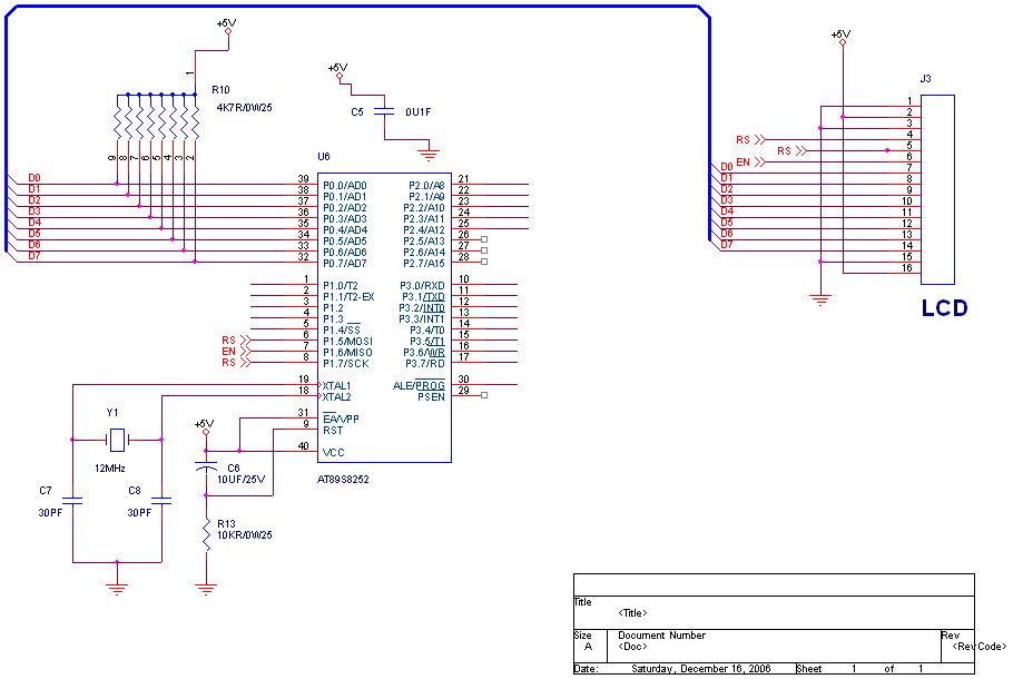
How to interface an LCD to the 89C51 microcontroller using 4-bit mode. A Lampex 16200 controller is being used; please send the manual for this controller. To interface an LCD with the 89C51 microcontroller using 4-bit mode, the following steps...
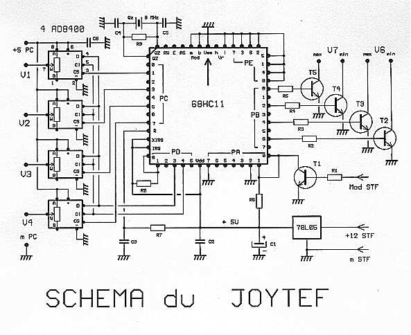
Using the software during flight simulation models of planes: REAL-FLIGHT, we first chose a housing of any transmitter empty direct connection potentiometers innings. However, this is not good because, first races of the potentiometers are only 90 degrees, which...
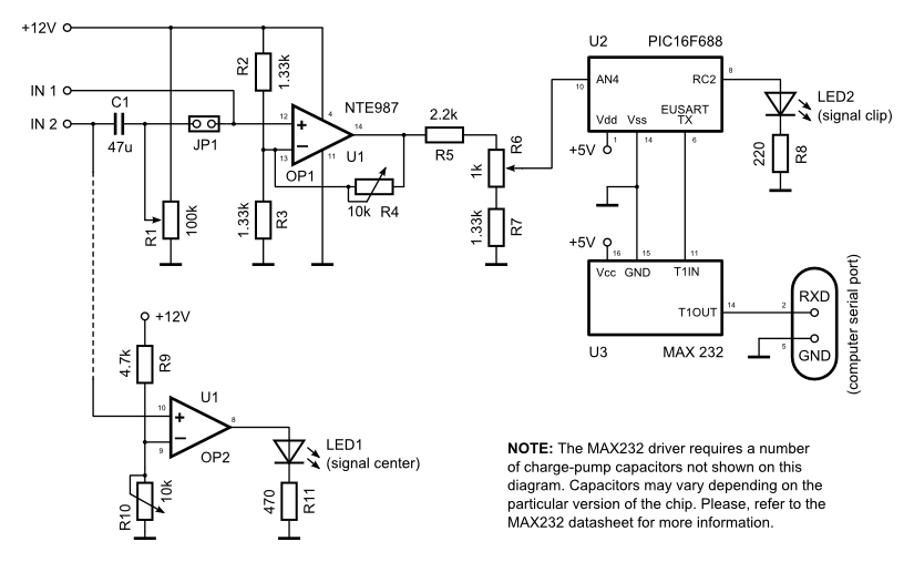
The data logger comprises a basic operational amplifier (op-amp) circuit that amplifies the input signal and transmits it to a PIC16F688 microcontroller for digitization, serialization, and subsequent transmission to a computer's serial port through a MAX232 serial driver. Some...