
rotating flashing 230v lights
The circuit design incorporates a 230V/24V center-tapped transformer (T1) to step down the mains voltage to a lower level suitable for rectification. The full-wave rectifier composed of diodes D5 and D6 converts the AC voltage to DC, while the Zener diode D4 ensures that the output voltage does not exceed 15V, providing voltage regulation and protection for downstream components.
The use of triacs D7, D8, and D9 allows for the control of high-voltage loads, making the circuit versatile for various lighting applications. The optoisolators (IC2, IC3, IC4) provide electrical isolation between the control circuitry and the high-voltage components, ensuring safety and preventing interference.
The operational amplifiers configured as monostable multivibrators (IC1A, IC1B, IC1C) create a timed output pulse, which, when cascaded, generates a sequential activation of the triacs, producing a rotating light effect. This is particularly useful for decorative lighting applications where a dynamic display is desired.
The astable multivibrator (IC1D) is designed to generate a continuous square wave output, allowing for the simultaneous flashing of all connected lamp strings in the Flash mode. The adjustable nature of this configuration enables customization of the flash rate, catering to different aesthetic preferences.
The circuit's capability to drive multiple 230V lamps in parallel, while adhering to the maximum current specifications of the triacs, ensures flexibility in lighting design. The inclusion of trimmers R1, R2, and R3 allows for fine-tuning of the timing characteristics, facilitating the creation of visually appealing light patterns. The option to replace trimmers with fixed resistors provides an alternative for those seeking a simpler assembly with less variability in performance.
Overall, this circuit is well-suited for applications requiring both rotating and flashing light effects, making it ideal for festive decorations and other lighting displays.The 15V dc supply is obtained from a nominal 230/24V center tapped ac transformer (T1) and a full wave rectifier (D5 & D6): Zener diode D4 was added to clamp the dc voltage to 15V maximum. Triacs D7, D8 and D9 are insulated from the control circuitry by means of Optoisolators IC2, IC3 and IC4.
IC1A, B and C are wired as monostables and cascaded in order to obtain a rotating sequence when the Mode switch SW1 is set in the Rotate position. IC1D acts as an astable multivibrator and generates an adjustable flashlight, driving all three lamp strings at the same time when the Mode switch SW1 is set in the Flash position. Each channel can drive several 230V lamps wired in parallel for each string, provided the maximum current of the Triacs is not exceeded.
For example, each channel will be able to drive up to 20 40W bulbs. The circuit is also well suited for many small bulbs wired in series like the usual Christmas tree lamp strings decorations. As these are very low power devices, a lot of them can be driven by this circuit. The more lamps per string are used, the more satisfactory will be the resulting effect. The Trimmers R1, R2 and R3 should be adjusted to obtain equal delay times or until a pleasing visual result is obtained when observed from some distance.
In any case, the Trimmers can be substituted by three fixed 1/4W resistors of equal value: 100K, 220K or 470K will work fine. 🔗 External reference
Related Circuits
Automatic color holiday lights circuit The automatic color holiday lights circuit is designed to control the operation of decorative lights during festive seasons. This circuit typically utilizes a microcontroller or a timer to manage the sequencing and color changes...
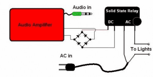
The basic Idea was to have Christmas lights flash with the music. In my design I use an ordinary amplified computer speaker, a diode bridge, and a ‘CRYDOM’ SSR (Solid State Relay). In order to increase the time that...
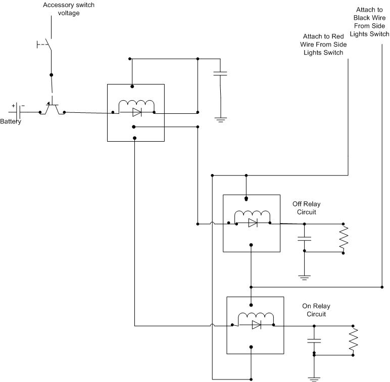
A decision has been made to install daytime driving lights for an Elise vehicle. The intention is to eliminate the need for manually pressing the button on and off repeatedly. The installation of daytime driving lights (DRLs) enhances vehicle visibility...
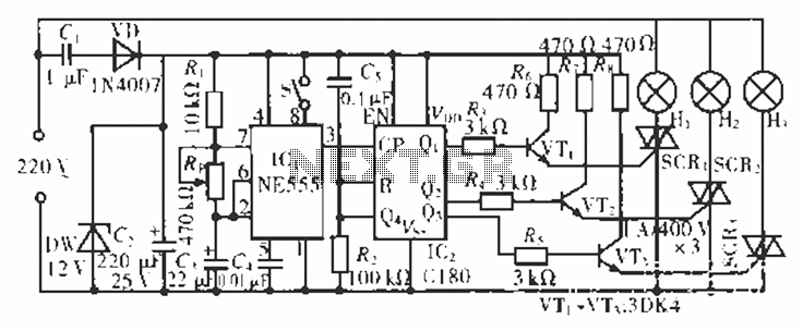
The circuit operates at 220 V AC using a C1 buck converter and a DW regulator. The VD ensures the entire stream is processed, and C2 provides a filtered output of 12 V DC for the voltage supply control...

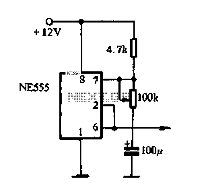
This circuit is a doorbell system featuring flashing LEDs to enhance its visual appeal. The integrated circuit IC1 (NE555) is utilized as a clock generator, configured as an astable multivibrator. The output frequency can be adjusted using the potentiometer...

The self-excited multivibrator circuit utilizes transistors VTi and VT2 to generate an output signal that triggers a thyristor (VT3). An adjustment potentiometer (RP) is incorporated to modify the oscillation frequency, which in turn adjusts the flashing cycles of lights...