
VOX (Voice-Operated Switch)
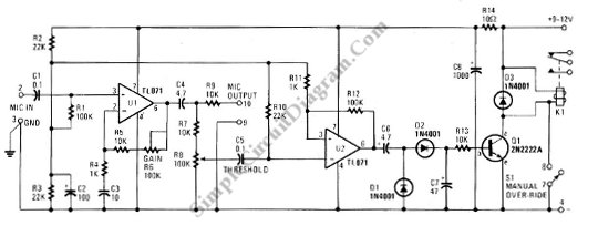
The VOX Box circuit operates as a voice-activated switch, utilizing a microphone to detect sound levels and subsequently control an output device through a relay. The primary components include a Schmitt trigger, which serves to convert the analog audio signal from the microphone into a clean digital signal, ensuring reliable switching action.
The microphone captures sound waves and converts them into an electrical signal, which is then fed into the Schmitt trigger. The Schmitt trigger's hysteresis characteristics provide noise immunity and prevent false triggering due to ambient noise. When the detected sound level exceeds a predetermined threshold, the Schmitt trigger outputs a high signal.
This high signal activates a relay driver, which is designed to amplify the signal sufficient to drive the relay coil. The relay, in turn, can control larger loads, such as lights or appliances, allowing them to be turned on or off based on voice commands.
The circuit may include additional components such as resistors and capacitors to set the sensitivity of the microphone and the timing of the relay operation. Proper design considerations must be taken into account to ensure that the VOX Box functions effectively in various environments, including the selection of the microphone type and the configuration of the relay to handle the intended load.
In summary, this VOX Box circuit provides a practical solution for creating voice-activated control systems, leveraging simple yet effective electronic components to achieve reliable performance.This schematic diagram below show a circuit of VOX Box (voice-operated switch). This circuit consist of a Schmitt trigger, a relay driver, and microphone.. 🔗 External reference
Related Circuits
Inquiry regarding the old Uni's Model 1221 amplifier, specifically seeking advice on switching from 6L6 tubes to EL34 tubes. The individual expresses a lack of expertise in tube amplifiers. The Uni's Model 1221 is a vintage tube amplifier that typically...
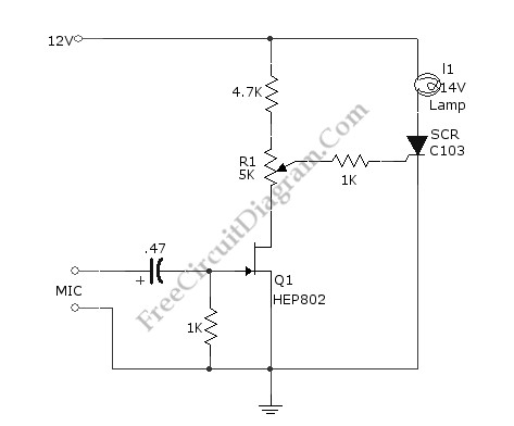
This simple circuit illustrated in the schematic diagram activates the switch using sound. It can be utilized for various applications, such as automatic (sound-controlled) disco lights or car LED light shows. The transistor Q1 amplifies the audio from the...
VOX is a voice-controlled switch commonly used for microphones, serving as a replacement for the traditional switching button. The actuating threshold is adjusted through the volume potentiometer. The VOX (Voice Operated Switch) circuit functions by detecting sound levels and activating...
This is a simple Vox AC amplifier. The circuit is not very clear but is readable. The circuit in question represents a basic Vox AC amplifier. The primary function of this circuit is to amplify the input audio signals, specifically...

This simple circuit shown in the schematic diagram activates the switch using sound. This circuit can be used for various applications, such as automatic switching. The circuit utilizes a sound sensor, which is typically a microphone or a piezoelectric sensor,...
VOX is a voice-activated switch commonly used with microphones as an alternative to traditional push-button switches. The VOX can be connected to various audio equipment featuring an external speaker for coupling. The activation threshold is adjusted using the volume...
Warning: include(partials/cookie-banner.php): Failed to open stream: Permission denied in /var/www/html/nextgr/view-circuit.php on line 713
Warning: include(): Failed opening 'partials/cookie-banner.php' for inclusion (include_path='.:/usr/share/php') in /var/www/html/nextgr/view-circuit.php on line 713