
RS-232 Laser Transceiver
The schematic for the transceiver includes essential components such as the MAX232A IC, which serves as the interface for the PC, and the OP505A photo-transistor, which detects the laser signal. The circuit is designed to ensure reliable communication over extended distances while maintaining low costs and ease of assembly for beginners. The overall design emphasizes safety, functionality, and adaptability for various laser-based projects.This project is designed for the entry level laser experimenter. The circuit allows any two computers with serial (RS-232) communication capability to communicate over 200 meters using a laser beam. A low cost transmitter only circuit is also presented here for use in one way communication and other laser based projects.
If you are like me and always wanted to buy a laser pointer to play with, but could never find practical uses for one, here are a couple of circuits to convince you to finally make that purchase. Before we begin, however, it is necessary to give a word of warning: Never look directly into the laser beam as eye damage may occur. I will present the project in 2 sections: the first is a full-duplex transceiver, and the second is a transmitter only.
The main reason for separating the design is to offer a cheaper solution if only half-duplex communication is required. For full-duplex communication 2 transceivers and 2 lasers will be required, and for half-duplex communication a single laser, a transmitter and a transceiver is needed.
The transmitter can be also used as a stand-alone circuit if you only want to control the laser in other laser experiments. This view shows the assembled transceiver. In this photograph you can see the conductive dummy battery used to reach the negative contact inside the case of the laser.
The laser source for this project is an inexpensive laser pointer pen. As well as being readily available, the circuit is designed in such a way so that the laser pointer is not damaged, and can be used for other experiments. Because this is an entry level circuit, costs have been kept to a minimum around $20 for the transceiver and approximately $10 for the transmitter (excluding the laser pointer).
Why use a laser A laser as a communications medium has some unique properties compared to other forms of media. A line-of-sight laser beam is useful where wires cannot be physically connected to a remote location.
A laser beam, unlike wires, also does not require special shielding over longer distances. Lasers offer at least an order of magnitude longer distances compared to infrared LEDs. Although RF transmitters may offer longer distances than line-of-sight lasers, they are subject to interference from other transmitters. Since the laser medium is line-of-sight and the beam being only several millimeters in diameter it is very difficult for the data stream to be tapped.
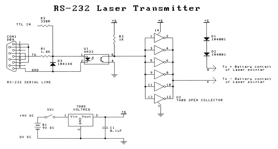
This offers secure communication since any attempts to intercept the laser beam would be detected at the receiver as a loss in data. A laser medium also allows for the sender and receiver to be galvanically isolated from each other. The transceiver is based on the MAX232A IC for generating and receiving RS-232 compatible voltage signals.
The receiving sensor is an NPN infrared photo-transistor (OP505A). I chose an infrared photo-transistor to minimise ambient light interference. Although the laser wavelength is in the visible spectrum (~670nm) the photo-transistor`s broad response band (550nm to 1050nm) is wide enough to sense the intense laser beam. The signal from the photo-transistor is buffered via a pair of Schmitt trigger buffers to clean up and square the signal.
The output of the second buffer is then directly converted to a RS-232 standard signal via the MAX232A. The MAX232A generates +10V and -10V voltage swings using a dual charge-pump voltage converter from a single +5VDC rail (see RS-232 standards below).
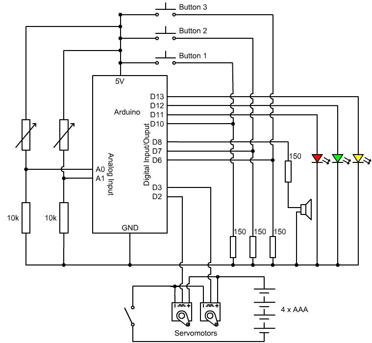
Several different versions of the MAX232 chip exist. The A version requires only 0. 1 uF capacitors for the charge-pump and inverter, whereas the MAX232 requires 1uF capacitors. The advantage of the A version is that it has faster response times, and allows for faster data rates. Figure 1. The schematic of the transceiver. The MAX232A IC provides the interface to the PC, a 🔗 External reference
Related Circuits
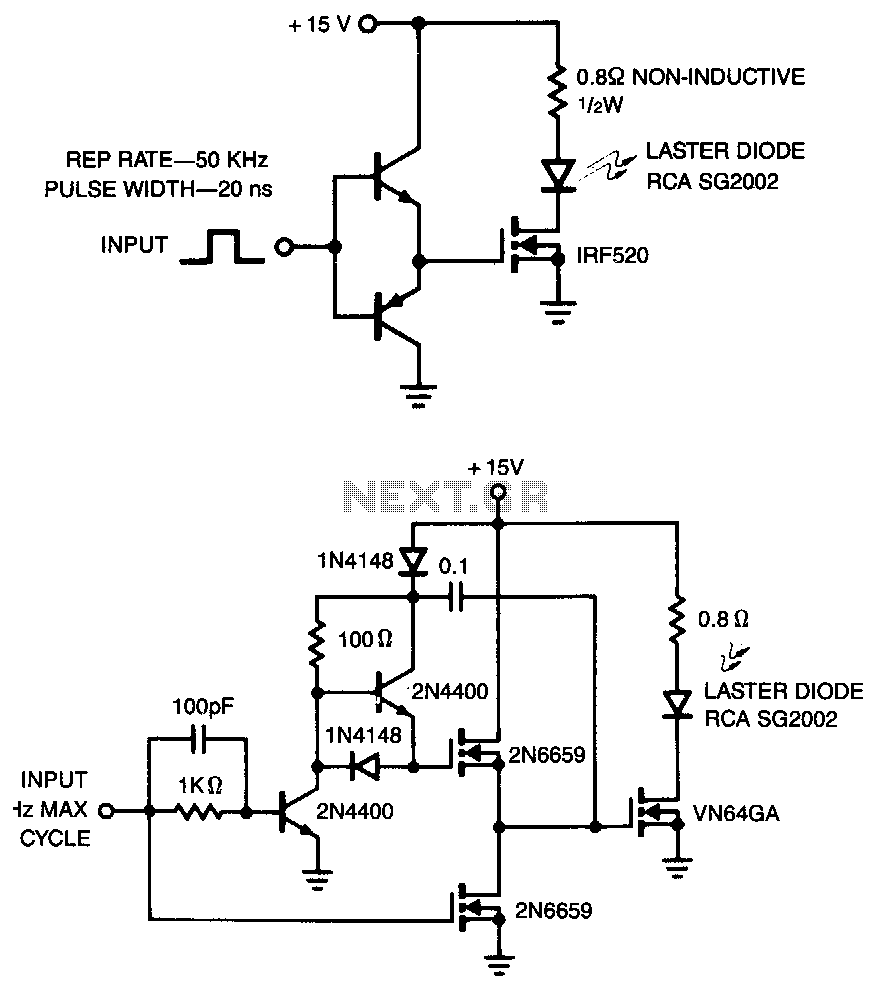
The laser diode pulser is a straightforward drive circuit designed to operate a laser diode with 10 A, 20 ns pulses. With a duty cycle of 0.1%, the repetition rate reaches 50 kHz. A complementary emitter follower serves as...
In general, the transceiver switches the 4-element 1500 ohm xtal BPF ends between the inputs and outputs of the two SA602s to reverse the signal flow for R/T operation. Since no IF amplifier is used in the design, 20...
The whole Construction: You can call the transceiver like this as "OZL type". Characteristics of the "OZL type" are as follows. 1. Single conversion super. 2. Using two DBM-s as modulator and converter. 3. Modulator DBM is used as...
Climber A ascends a route while Climber B remains on the ground, tracking Climber A's progress with a laser pointer. The Redpointer device records the exact route taken. In Mode 1, the recorded route is played back in real-time,...
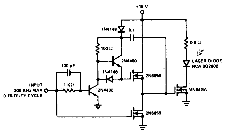
A faster driver can supply a higher peak gate current to switch the VN64GA very quickly. The circuit uses a VMOS totem pole stage to drive the high power switch. The described circuit employs a VMOS (Vertical Metal Oxide Semiconductor)...
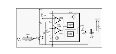
This circuit is designed around a 555 timer and utilizes a minimal number of components. Due to its simplicity, it can be easily constructed and operated by beginners. The circuit leverages the 555 timer IC, which is a versatile and...
Warning: include(partials/cookie-banner.php): Failed to open stream: Permission denied in /var/www/html/nextgr/view-circuit.php on line 713
Warning: include(): Failed opening 'partials/cookie-banner.php' for inclusion (include_path='.:/usr/share/php') in /var/www/html/nextgr/view-circuit.php on line 713