
ZXSpectrum128 plus 3 circuit service manual

START: CHECK TV TUNED OK. TRY CHANNEL 36. VOLUME UP. CONNECT PSU TO 240V AC MAINS. CONNECT TO TV SOCKET. HOLD DOWN BREAK KEY AND PLUG IN 9V LEAD INTO COMPUTER. If the RED LED lights up, the mains fuse is OK; otherwise, replace the fuse. If the picture or sound is not present on the TV, check the LED and PCB connector. If any picture appears, check the modulator and reset the button on the DC-DC converter. If the menu appears, press the down arrow. If no sound is detected, check ULA, CPU, RAM, and TEA 2000. If the blue bar on the menu moves, check the modulator and sound coil tuning. If all checks are OK, select 128K BASIC and press enter to check the keyboard connectors and ULA. Test all keys, and if any issues are found, rectify and retest. If all is OK, proceed with tape tests. The Spectrum +3 test software is contained on a ROM board that should be plugged into the Expansion I/O slot of the +3.
The Spectrum +3 diagnostic routines are crucial for identifying and resolving issues within the system. The initial step of resetting the machine while holding the BREAK key allows the user to access the test card display, a vital interface for troubleshooting. The subsequent action of pressing the QAZMLP keys prompts the system to display diagnostic information, guiding the user through a series of checks.
The diagnostic checks are methodically structured to assess the core functionalities of the drive mechanism and its associated components. Each parameter, such as motor rotation and read/write errors, is tested against predefined thresholds to ensure proper operation. For instance, the motor rotation must remain within a margin of 200 +/- 5 milliseconds, which is critical for maintaining the timing accuracy required for data processing.
In cases where errors are detected, the procedures outlined provide a systematic approach to isolate and diagnose the faults. The emphasis on checking wiring and adjusting components like the VR201 potentiometer underscores the importance of ensuring that physical connections and adjustments are correctly configured before considering component replacements.
Moreover, the flowchart-like structure of the diagnostic process facilitates a clear path for troubleshooting, allowing technicians to efficiently navigate through potential issues. Each step is designed to either confirm the functionality of a component or direct the technician to further investigate related systems, ensuring that no aspect of the diagnostic process is overlooked.
The comprehensive nature of the diagnostic routines, including the emphasis on potential software issues, reflects the complexity of the Spectrum +3 system. It is essential to rule out software malfunctions before proceeding to hardware diagnostics, as this can save time and resources in troubleshooting efforts.
In summary, the Spectrum +3 diagnostic routines represent a well-defined methodology for maintaining system integrity, ensuring that users can effectively identify and rectify faults within the machine. The structured approach not only aids in immediate troubleshooting but also contributes to the long-term reliability of the Spectrum +3 system.To invoke the Spectrum +3 diagnostic routines, first reset the machine while holding the BREAK key down. This will go into the test card dispray. Now hold down the QAZMLP keys for a few seconds unti the diagnostic title is displayed. Now follow the on screen prompts. This chart is for information only and does not guarantee an exact diagnosis. For warranty purposes and faulty drive mechanism must be returned to Amstrad for replacement. Service agents should not attempt any repairs on the mechanism or to it`s PCB part number 270312 Index period-N- Motor rotation 200+/- 5 msec | Y | Self-read error -N- Read Error | Y | Write error -N- Write Error | Y | Interchangeable-N- Interchangeability Error lead | Y | Disk Drive OK Motor Rotation | | Does motor-N-Power Supplied Rotate | | | | | | Y N Y<-<-| | | | | Check Wiring | | | Adjustable with-N-Does it rotate VR201 normally by using- | normal motor | Y | N | Y | Adjust Time to 200 | Replace drive +/- 1 ms Replace motor Read Error | | Test with disk EME - CF2 | | TR39 2F output-N-Head touch OK -N-Replace drive >= 140 mV | | | | Y Y | | | | Is head output-N-Replace head assembly Is TROO output-N 1 mV or more =< 220 mV | | | | | Y | Y | | | Read/write error | | in all tracks ->-+-Y->-Replace Drive | N | Read error only-N-Seek Error-N-Replace drive in Specific track | | | Y Y | | Replace disk | (inspect by drive) TROO output normal-N-Replace TROO | sensor | Y | | Replace drive Write Error | | Error Continous -N-Check action in-OK-Check action in | seek failure flow | read failure flow-+ | | | | Y | Amplifier System | | | | Head system | | | | Write waveform-OK->-+ | | in TP1. 2 | Replace drive | | | | NG | | | | | Head Connector-open-Repair head connector | open or short | | | |short | +-+ | | Replace control PCB Interchangable lead error | | + Off-track media-N-+ lead test | | | | | Y | | | | | - Off-track media-N-+-Adjust positioning lead test | | Y | | Index timing-N-Adjust index timing 0-1000 usec | | Y | | Media failure If a drive fault is reported the fault may be a software problem.
Before investigating the drive please carry out the following checks to ensure it is not a software problem. When the data is not restored by step 1, access the head to the adjacent track in the same direction as move previously, and thereafter return the head to the original track.
If the result is still incorrect even after the write operation is repeated more than 10 times, either the disc or the drive are working incorrectly. To find out the trouble source, carry out the read operations with another track. Should the error still be found. change the disk and repeat the above procedures. Should error still be found, the drive should be considered defective. If the error is removed, the original disk must be defective. Discard it. START-<-+ | | | | CHECK TV TUNED OK. TRY | CHANNEL 36. VOLUME UP | | | | | CONNECT PSU TO 240V | AC MAINS. CONNECT TO | TV SOCKET | | | | | HOLD DOWN BREAK KEY | AND PLUS IN 9V LEAD | INTO COMPUTER | | | | NO NO | RED LED LIGHTS UP ->-MAINS FUSE OK ->-REPLACE FUSE->-| | | | YES | | | | NO | YES | PICTURE/SOUND ON TV ->-+ +-CHECK LED, PCB->-+ | | | CONNECTOR | | YES | | | | | | NO | | PRESS AND RELASE ANY PICTURE->-CHECK MODULATOR, ->-| | RESET BUTTON AT ALL DC-DC CONVERTOR | | | | | | | NO |YES | | MENU APPREARS -+ | | | | | | | | YES | | | | | | | | YES | | PRESS DOWN ARROW | ANY SOUND -CHECK ULA, CPU->-| | | | |NO RAM, TEA 2000 | | | NO | | | | BLUE BAR ON MENU-+ | CHECK MODULATOR->-| | MOVES | | SOUND COIL TUNING | | | | | | | YES | | +->-CHECK ROM->-| | | | | | SELECT 128K BASIC | | | PRESS ENTER +->-CHECK KEYBOARD->-| | | | CONNECTORS, ULA | | | | | | TEST ALL KEYS | | | | | | | | NO | RECTIFY AND RETEST-<-| | ALL OK -+ | | | | | YES | | | | +->-+ DO TAPE TESTS The Spectrum +3 test software comes on a rom board.
This should be plugged into the Expansion I/O slot of the +3. The +3 should also have a loopbac 🔗 External reference
Related Circuits

This is a simple ultrasonic mosquito repeller circuit diagram. The circuit is designed based on the theory that pests like mosquitoes can be repelled by ultrasonic frequencies ranging from 20 kHz to 25 kHz. This ultrasonic mosquito repeller circuit...

Voltage Limiter Circuit Using Op-amp - Circuit Diagram, Waveform, Positive and Negative Voltage Limiters. The voltage limiter circuit utilizing an operational amplifier (op-amp) serves to restrict the output voltage to predefined levels, effectively preventing it from exceeding or falling below...
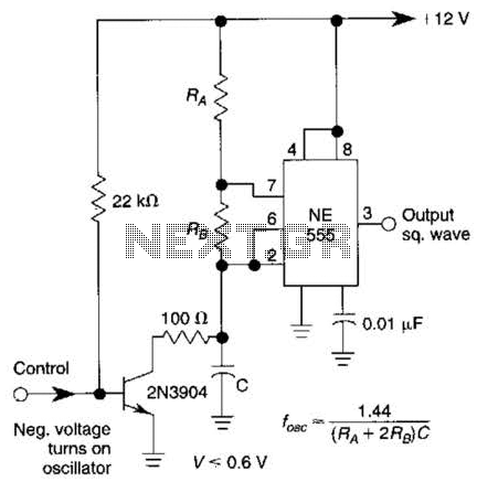
This gated 1-kHz oscillator provides a press-to-turn-on functionality, with waveforms available at the output of pin 3 and across capacitor CI. The gated 1-kHz oscillator circuit is designed to produce a square wave output that can be activated by a...
The design of this project relies heavily on sensors, which are present in both the control module and the robot. The computer analyzes the signals from these sensors to determine appropriate output actions. The control unit utilizes potentiometers as...
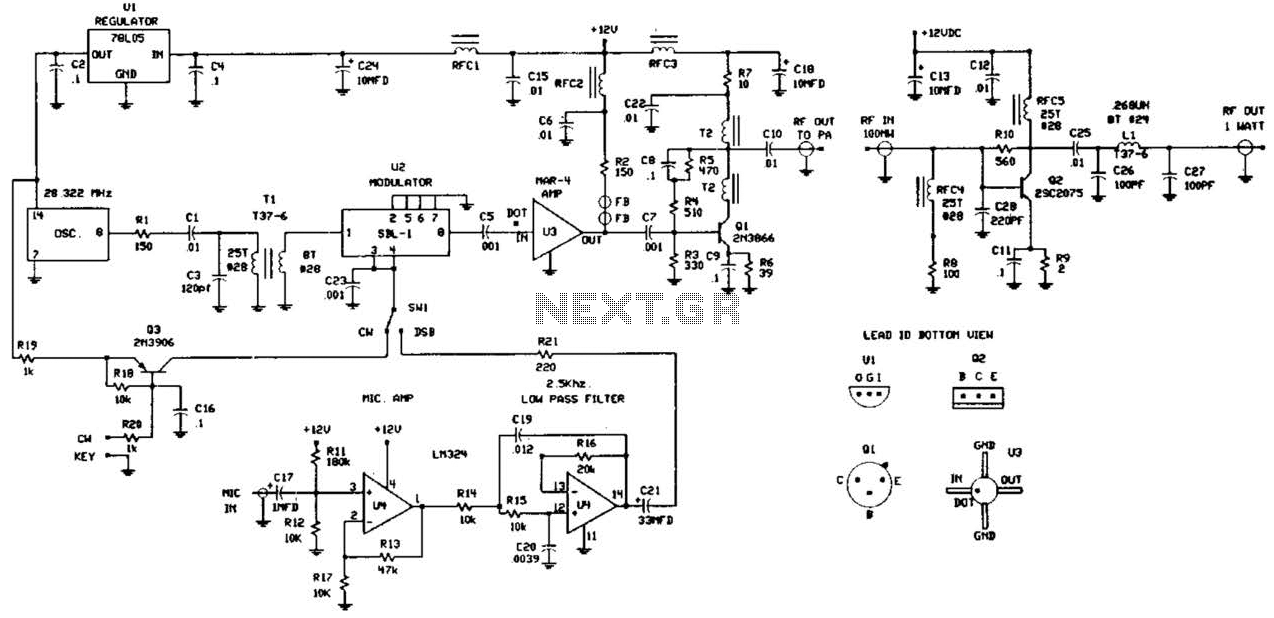
This circuit was detailed in a recent edition of an amateur radio magazine. It enables operation in the 160 to 190 kHz band with a maximum power output of 1 W (license-free) in various modes such as CW, SSB,...
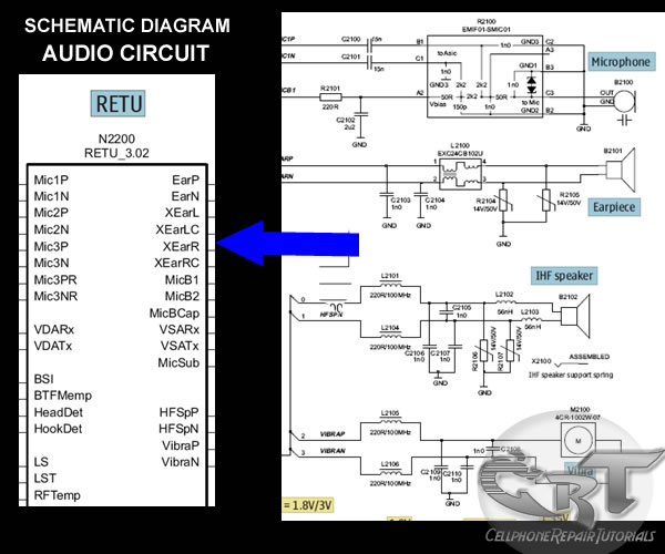
A mobile phone's microphone or mouthpiece is a component that converts sound signals into electrical signals. The earpiece speaker converts electrical signals back into sound signals, and similarly, the IHF, buzzer, or ringer speaker performs this function as well....
Warning: include(partials/cookie-banner.php): Failed to open stream: Permission denied in /var/www/html/nextgr/view-circuit.php on line 713
Warning: include(): Failed opening 'partials/cookie-banner.php' for inclusion (include_path='.:/usr/share/php') in /var/www/html/nextgr/view-circuit.php on line 713