
M5227 five-band equalizer circuit
The M5227P graphic equalizer circuit is structured to optimize audio signal processing by providing precise control over frequency bands. The logarithmic frequency axis allows for a more natural adjustment of audio levels, reflecting human hearing perception more accurately. Each of the five bands is centered at specific frequencies, allowing for targeted adjustments that can enhance or attenuate specific ranges of sound, thereby improving audio clarity and balance.
The use of octave selection for the center frequencies ensures that the equalizer can effectively manage the audio spectrum, allowing for broad adjustments across low, mid, and high frequencies. The large Q value facilitates a sharper response for each band, which is critical in minimizing overlap and interaction between adjacent bands. This characteristic helps maintain the integrity of the audio signal, preventing unwanted frequency bleed that could muddy the overall sound.
The resistances RGl and RChih play a crucial role in defining the equalization characteristics. By adjusting these resistances, the designer can tailor the equalizer's response to meet specific audio requirements, whether for live sound reinforcement or studio applications. The choice of a 2.7 kΩ value for these resistances is a design decision aimed at balancing input impedance and signal fidelity, ensuring that the equalizer can interface effectively with various audio sources without introducing distortion or loss of signal quality.
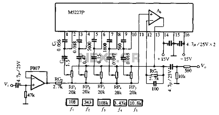
Overall, the M5227P circuit exemplifies a sophisticated approach to audio equalization, combining technical precision with practical usability, making it a valuable tool for audio engineers and sound designers seeking to refine their audio output.M5227P is the application circuit, for graphic equalizer, its control curve is always logarithmic frequency axis to represent rate, and require the same control curve pitch equal to ensure that the band is all in the maximum lift or total frequency attenuation response curve more evenly. In order to adapt to the requirements of the amount shown rate axis, the center frequency of each control segment rate shall octave selection. Meanwhile, in order to ensure that the adjacent control the interaction between the minimum band, the band have taken a large Q value and keep the band take the same zero value.
The circuit is a five-band equalizer, the center of the control section according to the frequency of three times the decadent process selection, namely: 108Hz, 343 H, 1.08kHz, 3.43kHz, 10,8kHz, take ' 1,8 a 1-5- value. In the circuit, RGl, R Chih resistance is mourning the band set the maximum lift amount and the amount of attenuation, the greater the resistance of each band promotion and also increases the amount of attenuation.
The feed circuit with 12dB increase, the amount of attenuation provided by the manufacturer according to the technical parameters, RGl, Rca were selected 2.7kflo Because the smaller the value, in order to increase the input impedance of the circuit at the input plus one level voltage follower. Each frequency response curve control integrated
Related Circuits
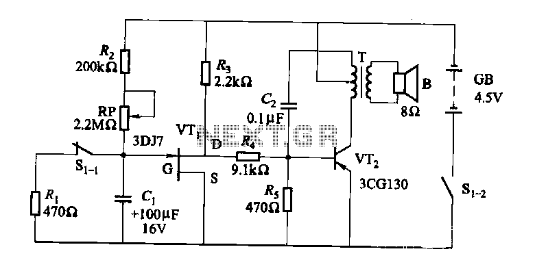
The darkroom circuit is designed for one-time exposure and emits an audible signal when the developing time is reached. This circuit can be utilized for photofinishing large timers and other applications. It comprises components such as FET VTi, resistors,...
This simple circuit can be used to charge a pair of AA or AAA-sized cells using solar energy. It has been utilized to maintain the operation of devices such as a Palm Pilot and a Walkman radio continuously. This...
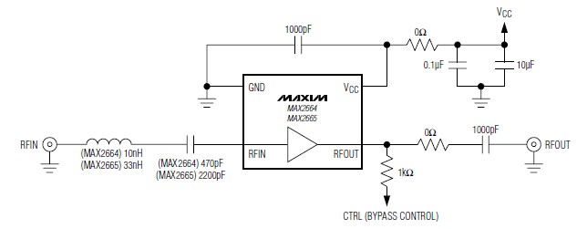
A simple, low-cost, and ultra-compact VHF/UHF low-noise amplifier circuit can be designed using the MAX2664 and MAX2665 ultra-compact LNAs for VHF/UHF applications. These devices incorporate a broadband LNA with an integrated bypass switch. The MAX2664 covers the UHF frequency...
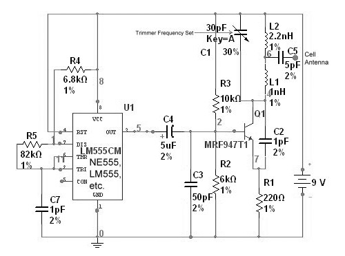
The circuit is based on the NE555 timer, functioning as a simple noise maker, with its output connected to a single transistor oscillator. This oscillator is designed to operate within a frequency range of 800 MHz to 2 GHz,...
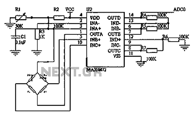
This circuit utilizes a BP01-type pressure sensor and the MAX4472 operational amplifier. The BP01 pressure sensor is specifically designed for blood pressure detection and is primarily used in portable electronic sphygmomanometers. It features a precision thick film ceramic chip...
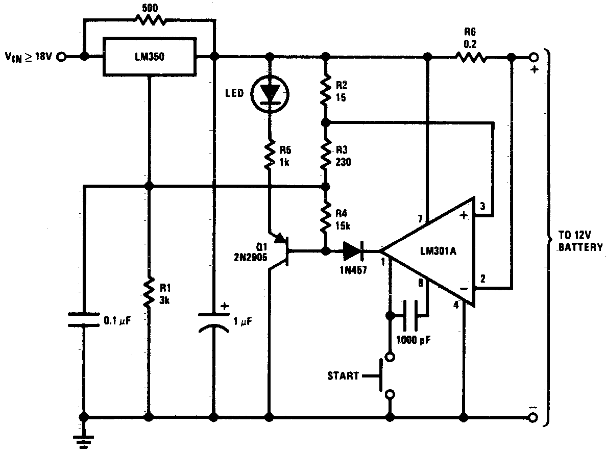
DC 12V Battery Charger Circuit Diagram. This circuit is a high-performance charger for gelled electrolyte lead-acid batteries. The DC 12V battery charger circuit is designed to efficiently charge gelled electrolyte lead-acid batteries, which are commonly used in various applications due...