
Phone line indicator using BF256B
This circuit is designed to detect whether any telephone connected to the same line is in use, indicated by an LED. The circuit is connected in parallel with the telephone line, which typically operates at a voltage of 50 to 60 V when idle. It utilizes a bridge rectifier composed of four diodes (D1 to D4) to safeguard the circuit from reverse polarity, ensuring reliable operation regardless of the connection orientation.
Under normal conditions, when no handset is lifted, the voltage across the line is stable, and the voltage divider formed by resistors R1 and R2 maintains the gate of the BF256B field-effect transistor (FET) in a non-conductive state. This prevents current from flowing through the LED. However, when a handset is lifted, the voltage on the line drops significantly, causing the FET to turn on and allowing current to flow through the LED, which lights up to signal that the line is busy.
The average current flowing through the LED is limited to approximately 10 mA, ensuring that the LED operates within safe limits while providing adequate visibility. The inclusion of a Zener diode (D5) serves to clamp the gate voltage to a maximum of 10 V, preventing any potential overvoltage conditions that could damage the FET. Additionally, a capacitor (C1) is employed to filter out any unwanted noise or transient pulses that may occur on the line, thereby enhancing the stability of the circuit's operation.
For calibration purposes, if the circuit does not perform as expected, it may be necessary to adjust the resistance value of R1, which is typically set at 220 KΩ. This adjustment can help fine-tune the voltage levels and ensure proper functionality across different telephone line conditions. The entire assembly can be powered by a 9V battery, and it is recommended to house the circuit in a small plastic enclosure to protect it from environmental factors. Caution is advised, as while 50 V is considered low voltage, it can still pose risks under certain circumstances.With this circuit can determine whether any of the phones of the same line is busy (it's up the handset), with the help of a LED.To circuit has no measurable effect on the telephone, so that there are problems with phone line company . The circuit is connected in parallel with the two wires of the telephone line. The bridge rectifier (D1. .. D4) at the entrance to protect the circuit from incorrect polarity. When none of the phones of the same line is not occupied then the voltage on the line is about 50 ...
60 V.I trend means the bridge and the voltage divider R1/R2 influences BF256B gate so that it will not conduct. Once you get up the handset of a device then the trend line is falling rapidly, and T1 conducts and LED lights, giving an indication of "busy".
Average T1 current flowing through the LED is limited to about 10mA. The Zener diode D5 prohibits the gate voltage of 10V to pass while the capacitor C1 acts as a filter for the parasitic pulses. If there are problems in the circuit should be replaced by the resistance R1 (220KO to be reasonable enough to adjust the voltage on the line).
The circuit operates comfortably with a 9V battery which together with the board can be placed in a small plastic box. Attention, the 50V line are true low voltage but nevertheless under certain conditions can be dangerous.
🔗 External reference
Related Circuits
This photocell is best mounted at tie level between the rails. The variable resistor adjusts the sensitivity of the circuit. This circuit can be powered by either 6 or 12 volts - BE SURE to use the proper relay;...
This schematic illustrates a simple DIY solar cell phone or USB charger circuit. It is designed to charge any device that can be powered from a computer USB port, such as MP3 players, cell phones, and iPhones. The circuit...
One of the drawbacks for some users is that Linux support for PIC microcontrollers is not widely known. The information is available, but the process of transitioning from writing C code to programming a chip has not been clearly...
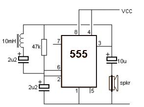
A simple metal detector circuit can be implemented using a 555 timer chip. The schematic diagram illustrates that this project requires only a few external electronic components. The metal detector circuit utilizing a 555 timer operates in astable mode, generating...
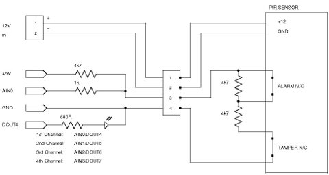
Security system sensors such as motion detectors, reed switches, pressure mats, glass-break detectors, infrared beams, and conductive film can be very useful for various applications, including home automation systems, interactive art installations, and security systems. Almost all security system...
Utilize this cell phone charger circuit along with a 1.5V battery when there is no main power available and charging your phone is necessary. This cell phone charger circuit is designed to provide a reliable charging solution using a 1.5V...