
rs-485 circuits
The interface commonly referred to as RS-485 is an electrical specification for multipoint systems utilizing balanced lines. RS-485 is similar to RS-422, but while RS-422 allows only one driver with multiple receivers, RS-485 supports multiple drivers and receivers. The specification document, TIA-485-A, outlines the electrical characteristics of the line, drivers, and receivers. Although there are brief suggestions regarding terminations and wiring, the standard does not cover connector pinouts or software protocols, unlike RS-232. An RS-485 network can accommodate up to 32 unit loads, with one unit load equating to an input impedance of 12k. By employing high-impedance receivers, the number of nodes can increase to 256. An RS-485 link can extend up to 4000 feet and achieve data transfer rates of up to 10 Mbps, though these rates cannot be achieved simultaneously. At 90 kbps, the maximum cable length is 4000 feet; at 1 Mbps, it reduces to 400 feet; and at 10 Mbps, it is limited to 50 feet. For networks requiring more nodes or longer distances, repeaters can be utilized to regenerate signals and initiate a new RS-485 line.
While the RS-485 standard does not specify protocols, most RS-485 links utilize familiar asynchronous protocols supported by UARTs in PCs and other computers. A transmitted word comprises a Start bit followed by data bits, an optional parity bit, and a Stop bit. RS-485 can be added to a PC via an expansion card or by connecting an RS-485 converter to an existing port, with converters available for RS-232 and USB interfaces. On microcontrollers, an RS-485 transceiver can be linked to any asynchronous serial port. Many network circuits require a port bit to control each transceiver's driver-enable input, typically utilizing the RTS output in RS-232 designed ports. If RTS is unavailable, any spare output bit can be employed. Most serial communication tools, including Visual Basic's MSComm, support RS-485 communications with RTS controlled through software. WCSC's COMM-DRV serial-port drivers offer built-in automatic RTS control.
The primary reason for the long-distance capability of RS-485 links is the use of balanced or differential signals. Two wires, typically a twisted pair, carry the signal voltage and its inverse. The receiver detects the voltage difference between these two lines. This configuration effectively cancels out common-mode noise that may couple into both wires. In contrast, interfaces such as RS-232 utilize unbalanced or single-ended signals, where the receiver measures the voltage difference between a signal voltage and a common ground. The ground wire often experiences noise due to carrying return currents for all signals in the interface, leading to potential misreading of transmitted logic levels. The data sheets for RS-485 chips designate the non-inverted line as line A and the inverted line as line B. An RS-485 receiver requires a specific voltage difference to function correctly.When a network needs to transfer small blocks of information over long distances, RS-485 is often the interface of choice. The network nodes can be PCs, microcontrollers, or any devices capable of asynchronous serial communications.
Compared to Ethernet and other network interfaces, RS-485`s hardware and protocol requirements are simpler and cheaper. The RS-485 standard is flexible enough to allow a choice of drivers, receivers, and other components depending on the cable length, data rate, number of nodes, and the need to conserve power. Several vendors offer RS-485 transceivers with various combinations of features. In addition, there are options for methods of terminating and biasing the line and controlling the driver-enable inputs.
In this article, I show several circuits for RS-485 networks. Even if you use prebuilt cards or converters, understanding the options will help you choose the right product and configure it to get the best results for your application. But first, a quick look at RS-485. The interface popularly known as RS-485 is an electrical specification for multipoint systems that use balanced lines.
RS-485 is similar to RS-422, but RS-422 allows just one driver with multiple receivers, while RS-485 supports multiple drivers and receivers. The specification document, TIA-485-A, defines the electrical characteristics of the line and its drivers and receivers.
There are brief suggestions relating to terminations and wiring, but unlike RS-232, there`s no discussion of connector pinouts or software protocols. An RS-485 network can have as many as 32 unit loads, with one unit load equivalent to an input impedance of 12k.
By using high-impedance receivers, you can have as many as 256 nodes. An RS-485 link can extend as far as 4000 ft. , and can transfer data at up to 10 Mbps, but not both at the same time. At 90 kbps the maximum cable length is 4000 ft; at 1Mbps, it drops to 400 ft, and at 10Mbps, to 50 ft. For more nodes or very long distances, you can use repeaters that regenerate the signals and begin a new RS-485 line.
Although the RS-485 standard says nothing about protocols, most RS-485 links use the familiar asynchronous protocols supported by the UARTs in PCs and other computers. A transmitted word consists of a Start bit followed by data bits, an optional parity bit, and a Stop bit.
Two ways to add RS-485 to a PC are on an expansion card and by attaching an RS-485 converter to an existing port. Converters for RS-232 and USB are available. On microcontrollers, you can connect an RS-485 transceiver to any asynchronous serial port. Many network circuits also require a port bit to control each transceiver`s driver-enable input. Ports designed for RS-232 communications can use the RTS output. If that`s not available, any spare output bit will do. Most serial-communications tools, including Visual Basic`s MSComm, support RS-485 communications with RTS controlled in software.
WCSC`s COMM-DRV serial-port drivers have automatic RTS control built-in. The main reason why RS-485 links can extend so far is their use of balanced, or differential, signals. Two wires, usually a twisted pair, carry the signal voltage and its inverse. The receiver detects the difference between the two. Because most noise that couples into the wires is common to both wires, it cancels out. In contrast, interfaces like RS-232 use unbalanced, or single-ended, signals. The receiver detects the voltage difference between a signal voltage and a common ground. The ground wire tends to be noisy because it carries the return currents for all of the signals in the interface, along with whatever other noise has entered the wire from other sources.
And noise on the ground wire can cause the receiver to misread transmitted logic levels. The chips` data sheets label the non-inverted RS-485 line as line A, and the inverted line as line B. An RS-485 receiver must see a voltage difference of 🔗 External reference
Related Circuits
The SE555/NE555 timer was first introduced by the Signetics Corporation around 1971. Pin connections and functions are as follows: Pin 1 (Ground) - This pin serves as the ground or common pin, representing the most negative supply potential of...
Commercial FM demodulation occurs at an intermediate frequency (IF) of 10.7 MHz. With a frequency deviation of ±75 kHz, the deviation of the IF carrier is approximately ±0.7%. This deviation allows for the conversion of FM to AM or...
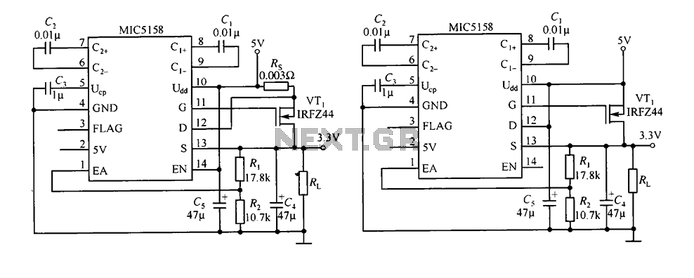
The circuit consists of peripheral components for the MIC5158, a linear regulator that converts a 5V input into a 3.3V output with a maximum current of 10A. When the input voltage (Ui) is 5V, an N-channel MOSFET, specifically the...
The telephone repeater is a circuit designed to amplify the call signal, making it louder than the original. This circuit has been developed in response to specific requests. The telephone repeater circuit functions by receiving the incoming audio signal from...
Remove the 6 mm screw that secures the lower rear fairing cover. This cover is the black plastic piece to which the spark plug protectors are attached. Only the machine screw should be removed; do not detach the lower...
A computerized infrared remote project is a simple device designed for recording and playing back streams of infrared data, specifically the codes transmitted by remote controls. Software is provided for use in both DOS and Windows environments, along with...
Warning: include(partials/cookie-banner.php): Failed to open stream: Permission denied in /var/www/html/nextgr/view-circuit.php on line 713
Warning: include(): Failed opening 'partials/cookie-banner.php' for inclusion (include_path='.:/usr/share/php') in /var/www/html/nextgr/view-circuit.php on line 713