
Rumble Mod Circuit For Steel Battalion
The Steel Battalion controller is a specialized input device designed to enhance the gaming experience for the Steel Battalion game, which is known for its complex control requirements. The controller features an extensive array of buttons, switches, and joysticks, all arranged to facilitate the operation of a virtual mech in the game.
The schematic diagram typically includes detailed information about the layout and connections of various components, such as analog joysticks, push buttons, and toggle switches. Each component is connected to a microcontroller that interprets the input signals and translates them into commands for the Xbox console.
Key features of the controller may include multiple analog inputs for precise control of movement, a variety of buttons for executing different actions, and possibly a force feedback mechanism to provide tactile feedback to the user. The controller's design would also need to accommodate proper ergonomics to ensure comfort during extended gameplay sessions.
The circuit design would involve considerations for power supply, signal conditioning, and communication protocols, such as USB or proprietary interfaces, to ensure compatibility with the Xbox system. The schematic would also detail the necessary resistors, capacitors, and other passive components that support the functionality and stability of the controller.
Overall, the comprehensive design of the Steel Battalion controller is a testament to the complexity of modern gaming peripherals, providing an immersive experience that closely simulates the operation of a mech in a battlefield scenario.This is the giant controller used for the game Steel Battalion for the xbox. I used this schematic diagram from a guy called Alpha who did it to his.. 🔗 External reference
Related Circuits
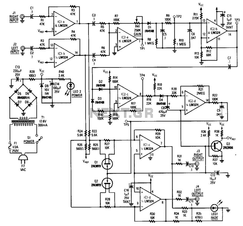
The LR inputs are summed, processed, and then drive a comparator. This comparator detects levels and generates transitions when audio inputs exceed or fall below predetermined thresholds. The frequency of these transitions, which correspond to rapid volume changes, is...
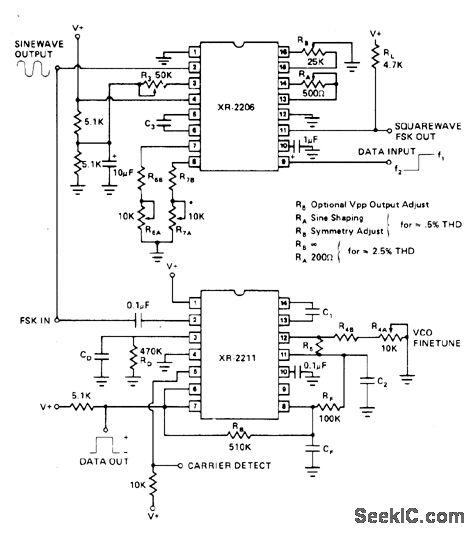
The values indicated are for a 13 kHz bandwidth, with 1070 Hz for the mark signal and 1270 Hz for the space signal. This utilizes the Exar XR-2206 function generator and the XR-2211 FSK demodulator. The report outlines the...
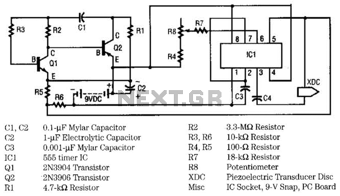
This circuit utilizes two transistors and one integrated circuit (555 timer IC) to generate a pulsating ultrasonic frequency. Transistors Q1 and Q2 are configured in a direct-coupled oscillator arrangement. The frequency of the oscillator is determined by capacitor C1....
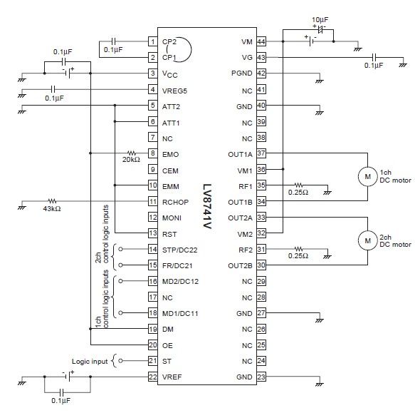
The circuit diagram illustrates an electronic project that requires a few external electronic components. The PWM current-control stepping motor driver IC can provide a maximum output current of up to 1.5 amperes. The configuration settings for the PWM current-control...
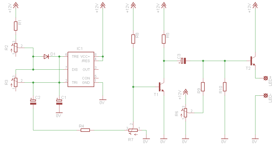
This circuit simulates a breathing or pulsing LED using a 555 timer chip. It has gained popularity, receiving numerous comments and emails from users who successfully built the circuit, as well as feedback from those who encountered difficulties when...
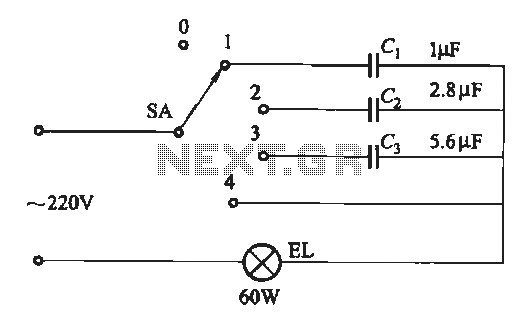
A dimming circuit capacitor circuit is illustrated in Figure 2-63. When the switch SA is moved from position "1" to "3," the capacitance increases in ascending order, resulting in the light bulb brightness also increasing correspondingly. When SA is...