
Running Message Display

The running message display circuit utilizes a combination of a decade counter and a timer to create a dynamic visual effect. The CD4017BC decade counter allows for sequential activation of outputs, which is ideal for driving the LEDs in a specific order. Each output corresponds to a letter in the message, and as the clock pulses are generated by the NE555 timer, the letters light up in succession, creating a visually appealing display.
The NE555 timer is configured in astable mode, providing a continuous square wave output at a frequency determined by the values of the resistors and capacitors used in the circuit. The adjustable potmeter VR1 allows for fine-tuning of the frequency, enabling users to control the speed at which the message is displayed.
Transistors T1 through T7 serve as switches that control the individual LEDs corresponding to each letter. When a transistor is activated by the output of the CD4017BC, it allows current to flow through the associated LED, illuminating it. The use of diodes, such as D21, ensures that the current flow is directed appropriately, allowing previously lit LEDs to remain illuminated even as new letters are activated.
The circuit's design is flexible, permitting the addition of more LEDs to create larger messages or intricate designs. This versatility makes it suitable for applications beyond simple displays, such as decorative lighting or fashion accessories. The ability to multiplex multiple circuits enhances the display effect, allowing for complex animations and moving messages, further expanding the creative possibilities for users. This project exemplifies the practical application of basic electronic components in creating engaging visual displays.Light emitting diodes are advan- tageous due to their smaller size, low current consumption and catchy colours they emit. Here is a running message display circuit wherein the letters formed by LED arrangement light up progressively.
Once all the letters of the message have been lit up, the circuit gets reset. The circuit is built around Johnson d ecade counter CD4017BC (IC2). One of the IC CD4017BE`s features is its provision of ten fully decoded outputs, making the IC ideal for use in a whole range of sequencing operations. In the circuit only one of the outputs remains high and the other outputs switch to high state successively on the arrival of each clock pulse.
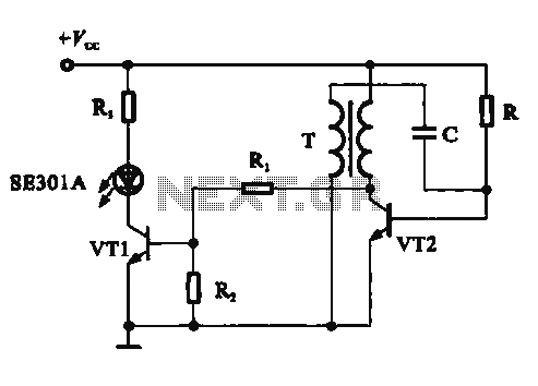
The timer NE555 (IC1) is wired as a 1Hz astable multivibrator which clocks the IC2 for sequencing operations. On reset, output pin 3 goes high and drives transistor T7 to on` state. The output of transistor T7 is connected to letter W` of the LED word array (all LEDs of letter array are connected in parallel) and thus letter W` is illuminated.
On arrival of first clock pulse, pin 3 goes low and pin 2 goes high. Transistor T6 conducts and letter E` lights up. The preceding letter W` also remains lighted because of forward biasing of transistor T7 via diode D21. In a similar fashion, on the arrival of each successive pulse, the other letters of the display are also illuminated and finally the complete word becomes visible.
On the following clock pulse, pin 6 goes to logic 1 and resets the circuit, and the sequence repeats itself. The frequency of sequencing operations is controlled with the help of potmeter VR1. The display can be fixed on a veroboard of suitable size and connected to ground of a common supply (of 6V to 9V) while the anodes of LEDs are to be connected to emitters of transistors T1 through T7 as shown in the circuit.
The above circuit is very versatile and can be wired with a large number of LEDs to make an LED fashion jewellery of any design. With two circuits connected in a similar fashion, multiplexing of LEDs can be done to give a moving display effect
🔗 External reference
Related Circuits
A tachometer can be constructed using the TC9400 in frequency-to-voltage (F/V) mode to convert frequency information (RPM) into a linearly proportional voltage. This voltage can then be compared to one of several comparators (in this example, using eight). The...
This circuit demonstrates a dynamic AC signal level display drive, which can be utilized for audio level display purposes. The AC signal detection and drive control are achieved using the BA6124 integrated circuit, along with five external colored light-emitting...

If the input is coming from a function generator's typical output clip leads, then the "black" lead or "-" or "ground" is connected to the circuit's ground. The ground of Pin 3 of a 555 timer must also be...

The schematic for this tutorial is illustrated below and includes all necessary components for the tutorial to function. The PIC programming circuitry is not included, as it is assumed that the PIC is either programmed externally or that the...
This project introduces a fundamental electronics building block: the counter. By building a simple circuit that increments the display count every second, the operation of displays and their control will be learned. For those already familiar with driving displays...
The figure illustrates a digital display pressure measuring circuit diagram. The circuit operates with an additional voltage of approximately 12.8V and draws a current of 30mA. Under maximum gain conditions, the input voltage range is 0.8mV. The zero adjustment...
Warning: include(partials/cookie-banner.php): Failed to open stream: Permission denied in /var/www/html/nextgr/view-circuit.php on line 713
Warning: include(): Failed opening 'partials/cookie-banner.php' for inclusion (include_path='.:/usr/share/php') in /var/www/html/nextgr/view-circuit.php on line 713