
Safety flare
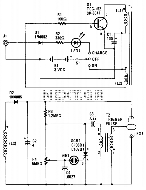
The described circuit functions as a high-voltage flash generator, utilizing a feedback oscillator mechanism to drive the operation of a transformer and subsequently trigger a flash tube. The oscillator is initiated by the switch SI, which energizes the components Q1, R1, C1, and the inductors L1 and L2. The operation of Q1 is critical, as it controls the saturation of the transformer core, thus regulating the energy transfer to the output circuit.
The transformer T1, designed with a ferrite core, enhances efficiency in energy conversion, allowing for a significant voltage increase at the secondary winding (L3). The rectification process carried out by diode D2 ensures that the output is converted to a usable DC voltage, which is then smoothed by capacitor C2. The voltage levels achieved (250 to 300 volts) are essential for the subsequent operation of the flash tube FX1, which requires high voltage to ionize the xenon gas and produce a luminous flash.
The charging of capacitors C3 and C4 through resistors R3 and R4 is a critical aspect of the timing and control of the flash rate. The adjustable resistor R4 allows for fine-tuning of the flash frequency, providing versatility in applications that require different flash rates. The activation of the neon lamp NE1 serves as a trigger mechanism for the silicon control rectifier (SCR1), which plays a pivotal role in discharging C3 into transformer T2, thereby generating a high-voltage pulse.
The output from transformer T2, rated at approximately 4 kW, is substantial enough to ensure that the flash tube FX1 emits a bright and intense flash upon the ionization of the gas. The rapid discharge of capacitor C3 through inductor L4 signifies the end of one cycle and the readiness for the next, demonstrating the circuit's ability to operate continuously without interruption. Overall, this design exemplifies a sophisticated approach to generating high-voltage flashes for various applications, utilizing feedback control and efficient energy transfer mechanisms.When SI is on, power is applied to an oscillator composed of Ql, Rl, Cl, LI, and L2. Coil Ll is the primary winding of Tl, and L2 is the feedback winding. When Ql turns on, its collector current saturates Tl's ferrite core. That, in turn, removes the base drive to Ql through L2. Transistor Ql then turns off. As the field around Ll and L2 decays, Ql will eventually turn on again, and the cycle repeats over, and over. Transformer Tl is a step-up, ferrite-core, potted-type unit whose secondary-winding (L3) output is rectified by D2 and filtered by C2, That capacitor charges up to around 250 to 300 volts, which is applied to the resistor divider composed of R3 and R4, along with the flash tube FX1.
Capacitors C3 and C4 will charge up to around 200 and 100 volts, through R3 and R4, respectively. Flash rate is adjustable via R4. When the charge on C4 gets to around 100 volts, neon lamp NE1 fires discharging C4 into the gate circuit of silicon control rectifier SCR1. The SCR1 turns on discharging C3 into the primary winding of trigger-pulse transformer T2. Transformer T2 is another step-up, pulse-type unit providing an output of around 4 kW across transformer T2's secondary winding.
The xenon gas inside FX1 is ionized and a bright flash is emitted. Finally, C3 quickly discharges through L4, and the cycle repeats over, and over. 🔗 External reference
Related Circuits
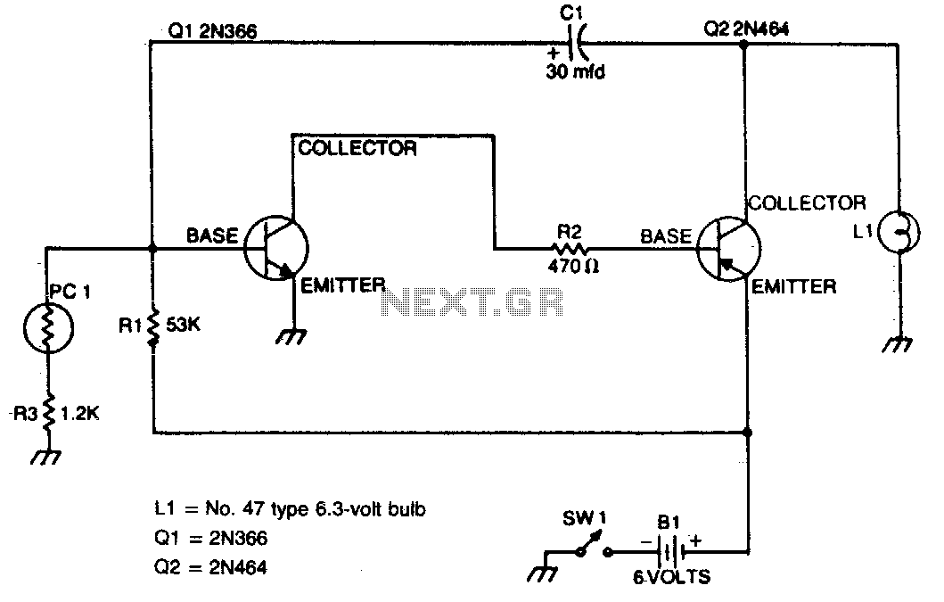
This flasher activates only during nighttime, providing bright illumination and automatically turning off when sunlight is detected. The photocell should be positioned on top of the unit to maximize light detection. The circuit for the nighttime flasher utilizes a photocell...
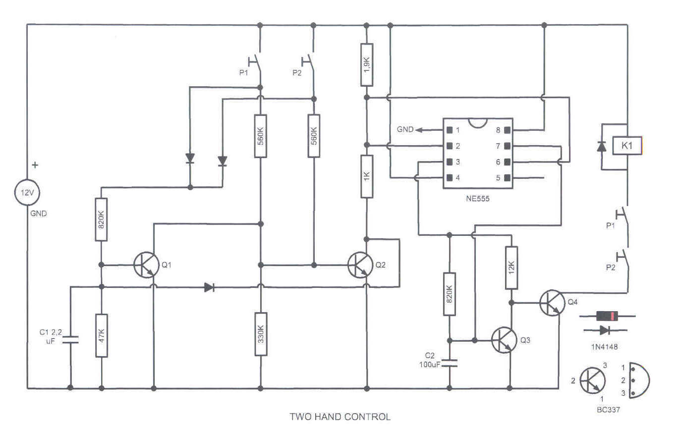
This circuit turns on a relay when two buttons are pressed at the same time. The relay backs off after a few seconds, then the buttons have to be released and pressed again. This feature is often required in...
The optical safety switch circuit includes a power supply circuit, a light control circuit, and a control implementation circuit (switch circuit). The power circuit is made up of a power transformer (T), a bridge rectifier (UR), and a filter...
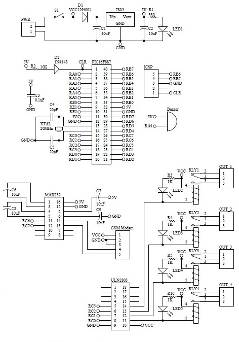
How to turn on equipment by sending SMS `1111` to switch it ON and switch off the equipment by sending SMS `0000`. The GSM switch will receive instructions for either load 1 (L1), load 2 (L2), load 3 (L3),...
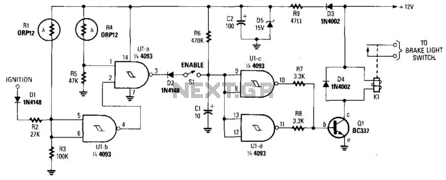
This circuit activates the brake lights of a parked car when headlights from an approaching vehicle are detected, alerting the driver of the oncoming vehicle about the stationary car. LDR4 serves as the sensor, while LDR1 deactivates the circuit...

To prevent deep discharge that can damage or shorten the life of a rechargeable battery, it is essential to disconnect its load before the battery is completely discharged. The circuit protects against AC line disturbances by switching off the...