
Arduino Online Thermometer circuit
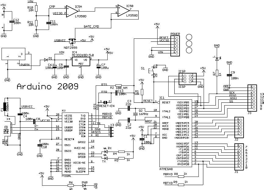
The online thermometer project utilizes an Arduino microcontroller as the core processing unit, interfaced with multiple temperature sensors to monitor environmental conditions. The sensors can be of various types, such as thermistors or digital temperature sensors like the DS18B20, which communicate via a one-wire protocol. This allows for multiple sensors to be connected in parallel on a single data line, facilitating efficient data collection.
The Ethernet shield, typically based on the W5100 or W5500 chip, enables network connectivity, allowing the Arduino to send temperature data to a cloud service for remote monitoring. The integration with Pachube (now known as Xively) enables real-time data visualization and logging, which is essential for maintaining optimal conditions in critical environments like server rooms or laboratory settings.
The schematic should include the Arduino connected to the Ethernet shield, with the temperature sensors connected via their respective data lines. Power distribution should be clearly indicated, ensuring that each sensor receives the necessary +5 VDC and ground connections. The RJ-45 connector wiring should be detailed, highlighting the T568B standard pinout for clarity. Additional components, such as resistors or capacitors, may be included in the schematic to ensure signal integrity and stability.
The breadboard layout should be illustrated to show how the components are arranged, with clear indications of where the sensors are connected and how the Ethernet shield is interfaced. Proper labeling of all connections and components will facilitate troubleshooting and future modifications to the circuit. The final schematic will serve as a comprehensive guide for constructing the online thermometer, ensuring that all necessary connections are made and that the system operates effectively within the intended applications.I havebeen researching a project which will help me with my understanding of electronics, networking, and programming. I decided to build an online thermometer which could be used in applications that need temperature monitoring.
I currently work in a lab environment where I test, troubleshoot, and calibrate equipment which is installed in nuclear power plants. Each module must have a burn in time ranging from 24 hrs to 360 hrs per module under max load conditions. I could use my online temperature sensor to monitor the efficiency of the cooling system in the burn in area.
Other applications could be the monitoring of a server room. The Arduino allows up to 6 sensors to be installed so this would be efficient to monitor a normal sized server room. I could use a program called Pachube to monitor the temperature ranges over time and see where the servers and equipment get the warmest.
This could then be tied into another program which could give an administrator a warning e-mail if the room temperature suddenly started rising. I first need a network cable to connect my ethernet shield to a router ( if connecting straight to a computer the cable will need to be a crossover cable).
Spread out twisted pair wires. I aligned them according to the T568B standard because it is more common in the industry. Here`s a diagram of both options and a pinout of a crossover cable. Insert the cut wires into an RJ-45 plug withwhite/orange wire on the left side. Make sure that the plastic insertion tab is facing down. Also ensure that the wires are pushed in far enough by inspecting the end. If you can`t see the wire all the way to the end then push wires in further before crimping. The great thing about the Seeed ethernet shield is they leave room on the board to terminate wires and components. However the version that I got will still require a breadboard for some external components. I don`t mind thought because I love working with breadboards! The temperature sensors will need a +5 VDC, Ground, and Data wire connected to work. I will need to terminate each data line accordingly from the ethernet shield: I skipped the first few pins and started with 3 because 0 and 1 are used for the serial connection to the host.
Pin 2 is used by the Ethernet shield to communicate with the arduino as seen in Figure 1. I started out by soldering my +5VDC wire so I can have for the +VCCon my breadboard. For the wire I just used some network cable without the sheathing. Now a continuity check with a DMM to ensure connectivity at all points. I`m using a paperclip on my negative lead to push through the breadboard to make a proper connection. It`s nowtime to attach the temperature sensors to the breadboard. I`m going to use network cable for the 3 pin terminations. First solder the sensor to the twisted pair wires with shrink tube in place. I have now attached my assembled circuit to my laptop via USB. I have also attached it to my router with the network cable I built ( you can connect this directly to you PC with a crossover cable).
🔗 External reference
Related Circuits

Some good inverter circuits I found oscillate at approximately 50 to 60 Hz. They are likely capable of handling up to two amps; any more than that will cause them to automatically shut off. If there are questions, please...
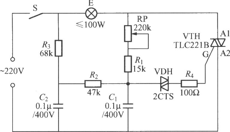
To address the lag and light transition issues, a Triac dimming light circuit featuring a dual time constant can be employed. This circuit enhances the resistor-capacitor network formed by R3 and C2. The reduced charge on capacitor C1 can...
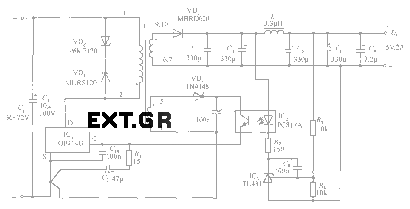
The circuit diagram includes an input filter capacitor C1 and a primary clamp composed of VDz and VD1. The resistor R1 is connected to the control terminal. C2 serves as a bypass capacitor. The TOP414GC-S is connected in parallel...
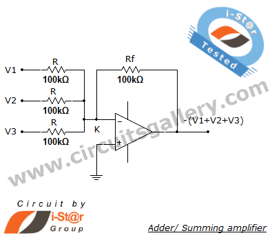
A summing amplifier, also known as an adder, is utilized to combine two or more signal voltages. This voltage adder circuit is straightforward and allows for the addition of multiple signals. It has a wide range of applications in...
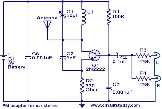
This compact FM adapter circuit, when connected to the audio output of a cassette player or iPod, enables the user to listen to their favorite music through a car stereo. It is particularly useful for vehicles that lack an...

Application of the differential amplifier circuit in OTL amplifier circuits. The differential amplifier circuit is a fundamental building block in various electronic applications, particularly in output transformerless (OTL) amplifier circuits. An OTL amplifier is designed to drive loads directly...