
Sawtooth and Squarewave Oscillator
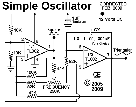
The described circuit involves a printed circuit board (PCB) with a control mechanism that allows for the adjustment of capacitance values. The specified capacitance values—100 pF, 470 pF, 0.001 µF (1 µF), 0.0022 µF (2.2 µF), 0.01 µF (10 µF), and 0.047 µF (47 µF)—are crucial for tuning the circuit to achieve specific frequency outputs.
Each capacitance setting corresponds to a set of measured frequencies, indicating that the circuit is likely part of a frequency generator or oscillator configuration. The frequencies listed suggest a range of applications, from audio signal processing to RF transmission, depending on the desired frequency output.
The variation in measured frequencies due to capacitor tolerances emphasizes the importance of selecting capacitors with appropriate specifications for precise applications. Capacitor tolerances can affect the stability and accuracy of the circuit, which may be critical in applications such as communication systems or audio equipment where frequency fidelity is paramount.
To create a comprehensive electronic schematic based on this description, one would typically include components such as capacitors, resistors, and possibly inductors, depending on the intended application. The schematic would illustrate the connections between these components and indicate how the control mechanism interacts with the capacitors to modify the output frequency. Additionally, it would be beneficial to include notes on the expected performance characteristics and potential sources of error due to component tolerances.
In summary, this circuit design highlights the interaction between capacitance and frequency, showcasing the need for careful component selection and adjustment to achieve the desired operational outcomes.With the Control "On the PCB", set at these Positions* CX = CW Center CCW 100 pf = 6, 400 hz 12, 050 hz 26, 000 hz 470 pf = 1, 525 hz 3, 200 hz 7, 232 hz. 001 uf = 681 hz 1, 425 hz 3, 250 hz. 0022 uf = 348 hz 619 hz 1, 540 hz. 01 uf = 69 hz 146 hz 340 hz. 047 uf = 16 hz 34 hz 88 hz. 1 uf = 7 hz 14 hz 34 hz These were Measured Freq uencies with "Typical" Capacitors. Due to Capacitor Tolerances, Your Results Will Vary a little. 🔗 External reference
Related Circuits
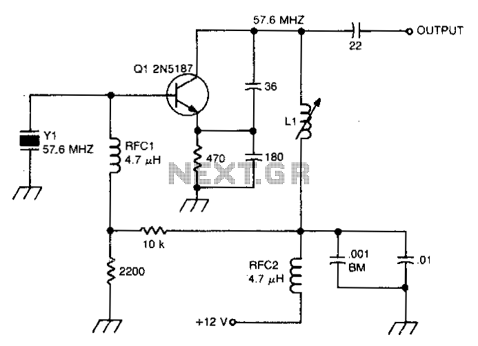
This circuit isolates the crystal from the DC base supply using an RF choke for improved starting characteristics. The circuit design features an RF choke that serves as a crucial component for isolating the crystal oscillator from the DC base...
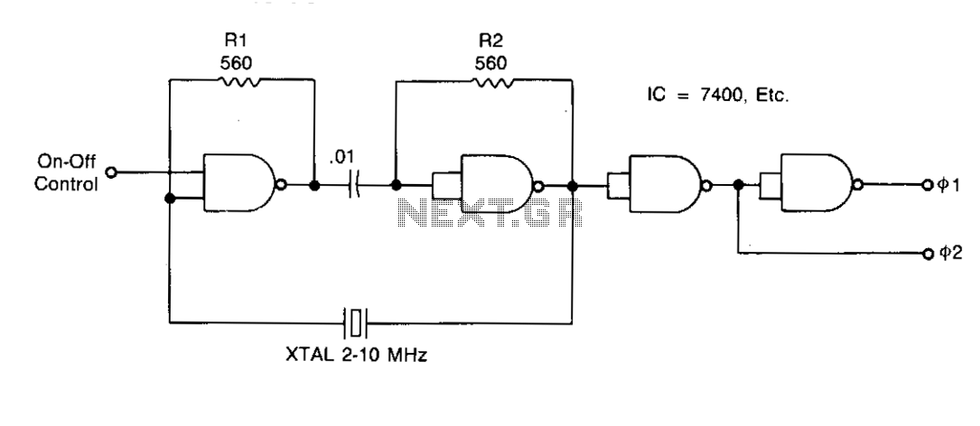
Resistors R1 and R2 stabilize the temperature of the NAND gates and ensure that the gates operate within a linear region during startup. Capacitor C1 acts as a DC block and must have an impedance lower than Vw at...
A sawtooth wave generator circuit using a 555 IC is presented in the article below. The frequency equation is provided with the supply voltage Vcc. The sawtooth wave generator circuit utilizing a 555 timer integrated circuit (IC) is a fundamental...
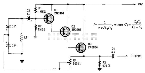
Essentially, this is a Hartley oscillator utilizing a triple-emitter follower, suitable for audio and low radio frequencies. The frequency is determined by the components, and at 1 kHz, a typical capacitor value would be 4.7 µF tantalum, although this...
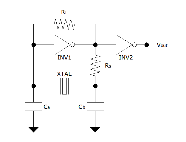
The Pierce oscillator is a simple circuit that, like the ring oscillator, utilizes inverters, though typically only one inverter is required. Its operational principle differs significantly from that of the ring oscillator, as it employs the inverter in its...
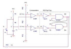
The 555 Timer IC operates in three modes: monostable, astable, and bistable/Schmitt trigger. This article will focus on its astable mode. The astable mode of the 555 Timer IC is characterized by its ability to generate a continuous square wave...