
Low-Frequency Lc Oscillator

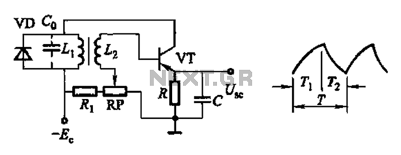
The Hartley oscillator is a type of LC oscillator that generates sine waves and is characterized by its use of an inductor-capacitor (LC) tank circuit. In this configuration, the triple-emitter follower serves as an amplifier stage, providing high input impedance and low output impedance, which is beneficial for driving subsequent stages or loads without significant signal loss.
The frequency of oscillation (f) for a Hartley oscillator can be expressed by the formula:
\[ f = \frac{1}{2\pi\sqrt{L_{total}C}} \]
where \( L_{total} \) is the total inductance of the two inductors used in the circuit, and \( C \) is the capacitance of the capacitor in the tank circuit. The inductance values can be adjusted to achieve the desired frequency, along with the capacitor value, which in this case is suggested to be around 4.7 µF for operation at 1 kHz.
In practical applications, the choice of components can affect the stability and performance of the oscillator. Tantalum capacitors are preferred in this scenario due to their stability and reliability at low frequencies. The use of a triple-emitter follower configuration allows for better thermal stability and improved linearity in the output waveform, which is crucial for audio applications.
Additionally, it is important to consider the power supply requirements and the overall circuit layout to minimize noise and interference, ensuring a clean and stable oscillation. Proper bypassing and decoupling techniques should be employed to maintain signal integrity throughout the circuit. This oscillator can be effectively used in various audio applications, including signal generation, tone generation, and modulation tasks, making it a versatile choice for electronic design projects. Basically a Hartley oscillator using a triple-emitter follower, this oscillator can be used at audio and low ra dio frequencies. The frequency is given by: At 1 kHz, typically C would be 4.7 ¥ tantalums, but this is only a guide as to convenient values to use.
Related Circuits
The voltage Vc1 increases linearly when the pull-up resistor RA in the monostable circuit is replaced with a constant current source, resulting in a linear ramp. The circuit for generating the linear ramp and the corresponding waveforms are illustrated...
A PLL (Phase-Locked Loop) oscillator is utilized to achieve a very stable frequency with minimal distortion in the sine wave output. Its stability is comparable to that of crystal-based oscillators, while the distortion level of the sine wave output...
To generate a 1 MHz square wave, it is advisable to use a higher frequency crystal and divide it down for two reasons: (1) 4 MHz crystals are generally more affordable and easier to procure than 1 MHz crystals;...
Common non-sinusoidal oscillator circuit, waveform and frequency formula - pulse wave oscillator - single-junction transistor blocking oscillator. The common non-sinusoidal oscillator circuit described is a pulse wave oscillator that utilizes a single-junction transistor in a blocking configuration. This type of...
An incandescent lamp has been utilized to reduce harmonic distortion in a sine oscillator circuit. The nonlinear resistance characteristic of the lamp filament assists in this process. In the context of electronic circuits, the use of an incandescent lamp as...
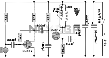
The following schematic diagram shows the design of a 100 MHz Radio Frequency RF Oscillator Circuit. The electrets microphone picks up and amplifies sound then fed it into the audio amplifier stage built around the first transistor. The output...