
Simple NE555 Sawtooth Wave Generator Circuit

The sawtooth wave generator circuit utilizing a 555 timer integrated circuit (IC) is a fundamental design in electronics, often used in applications such as signal generation, waveform shaping, and timing functions. The 555 timer can be configured in astable mode to produce a continuous sawtooth waveform.
In this configuration, the circuit consists of a 555 timer, resistors, and a capacitor. The frequency of the sawtooth wave is determined by the values of the resistors (R1 and R2) and the capacitor (C). The frequency (f) can be approximated by the equation:
f = 1.44 / ((R1 + 2 * R2) * C)
Where:
- R1 is the resistance connected between the discharge pin (pin 7) and the supply voltage (Vcc).
- R2 is the resistance connected between the discharge pin (pin 7) and the threshold pin (pin 6).
- C is the capacitance connected between the threshold pin (pin 6) and ground.
The output frequency of the sawtooth waveform is directly influenced by the supply voltage (Vcc). As the supply voltage increases, the frequency may also increase, depending on the resistor and capacitor values. The sawtooth waveform generated has a linear rise and a rapid fall, making it suitable for applications requiring a ramp signal.
In practical applications, the circuit may also include additional components such as diodes for protection, potentiometers for adjustable frequency, and filtering capacitors to smooth the output waveform. The design can be adapted for specific requirements by selecting appropriate component values to achieve the desired frequency and amplitude characteristics.A sawtooth wave generator circuit using a 555 IC is given in the article below.Frequency equation is given with the supply voltage Vcc.. 🔗 External reference
Related Circuits
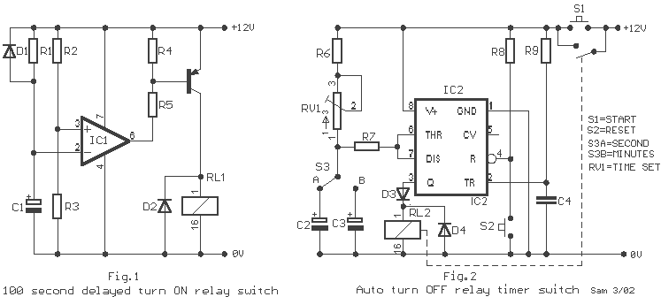
A 100 second delayed turn ON relay RL1 switch, if plug power +12V in circuit. In Fig.2 see a two range 6-60 second and 1-10 minute auto turn off relay timer circuit, with 555. Part List R1=1 Mohms C4=100nF...
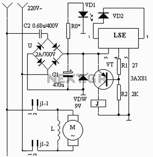
The circuit operates based on the interaction between an infrared light-emitting diode (VD1) and an infrared receiver diode (VD2). When VD1 emits infrared radiation, it is detected by VD2, which causes a decrease in its internal resistance. This change...
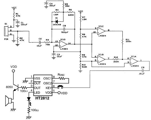
The operational amplifier IC1D modifies the frequency response to enhance the frequencies generated during motion detection while eliminating others, such as noise or gradual temperature variations. When the output voltage of IC1D exceeds 1.67V, it activates pins 8 and...
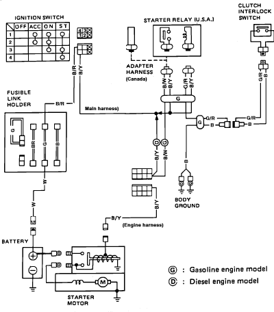
Nissan Sentra 1.6 Liter Manual Transmission Starter Circuit Wiring Diagram. The Nissan Sentra 1.6 Liter manual transmission starter circuit wiring diagram provides a visual representation of the electrical connections involved in the starting system of the vehicle. This diagram is...
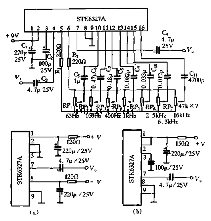
After the universal application of graphic equalizers, a new type of equalizer known as the parametric equalizer has emerged. This equalizer differs in its internal circuit structure and utilizes an external adjustment method that sets it apart from traditional...
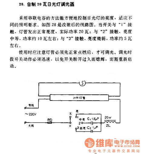
A homemade 20W fluorescent lamp dimmer utilizes a series capacitor connection to effectively control the brightness of fluorescent lamps, allowing for adaptability to various lighting requirements. In the modified circuit diagram (Figure 28), when the switch is set to...