
SBC Power overvoltage protection circuit diagram
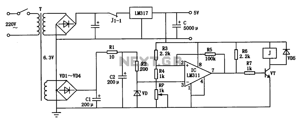
This circuit serves as a protective mechanism for Single Board Computers (SBCs) by regulating the input voltage to a safe level of +5V. It is essential to prevent over-voltage conditions that could potentially damage sensitive electronic components within the SBC.
The circuit typically includes a voltage regulator, which is designed to maintain a constant output voltage despite variations in input voltage or load conditions. Commonly, a linear regulator or a buck converter may be employed, depending on the efficiency requirements and the input voltage range.
In addition to the voltage regulator, the circuit may incorporate protective elements such as diodes, capacitors, and fuses. Diodes can be used to prevent reverse polarity, ensuring that the SBC receives power only in the correct direction. Capacitors can smooth out voltage fluctuations, providing stability to the power supply. Fuses or resettable polyfuses can protect against overcurrent conditions, disconnecting the power supply in the event of a fault.
The layout of the circuit should be designed to minimize noise and interference, which can adversely affect the performance of the SBC. Proper grounding techniques and decoupling capacitors should be employed to enhance the reliability of the power supply circuit.
Overall, this circuit is critical for maintaining the integrity and longevity of SBCs by ensuring that they receive a stable and safe operating voltage. Circuit as shown, can be used for operating voltage of + 5V SBC power to prevent damage due to over-voltage power supply throughout the SBC.
Related Circuits

The thermostat electric circuit operates as depicted in the figure. It has three settings: off, low power (Lo), and high power (Peru HL). When the DIP switch SA is set to the Lo position, 220V AC is directed through...
This is a simple regulated power supply circuit based on the well-known LM723 voltage regulator, which drives a transistor Q1 (2N3055). The output voltage regulation is achieved using potentiometer R1, allowing for an adjustable range from 0V to approximately...
National Semiconductor (NS Company) produces audio integrated circuits (ICs) that offer wide frequency response and low noise. These circuits provide excellent performance across all NS products. The circuit illustrated in Figure 3-12 includes a preamplifier and a singing equalizer...
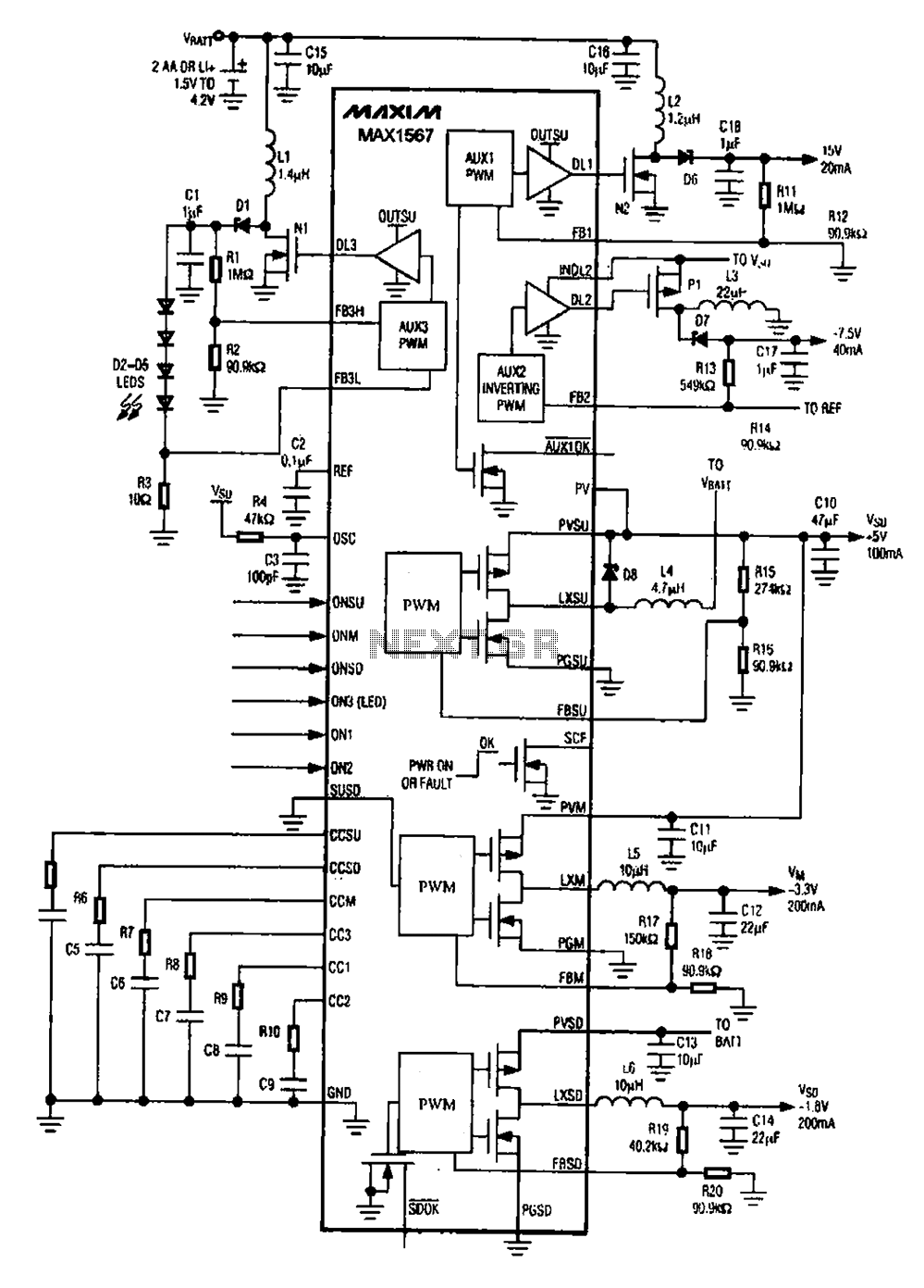
A brush 6-channel camera power supply circuit utilizing the MAX1566/1567. This circuit features a PWM generation system that is divided into six groups, with each group managing a separate channel. The circuit converts the DC voltage from the battery...
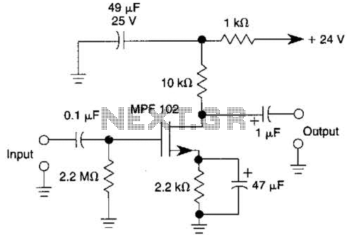
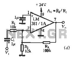
This JFET preamplifier has a gain of approximately 20 dB and a bandwidth exceeding 100 kHz. It is useful as a low-level audio amplifier for high-impedance sources. The described JFET (Junction Field Effect Transistor) preamplifier is designed to amplify low-level...
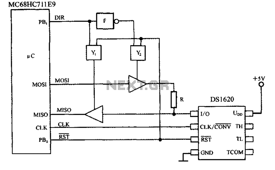
This circuit features a three-wire serial interface for smart temperature sensors, specifically the DS1620, along with an SPI bus interface circuit. The DS1620 is a high-accuracy digital temperature sensor that communicates over a three-wire interface, which consists of a data...