
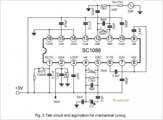
SC1088 AUTO SEARCH TUNING FM RADIO RECEIVER
The SC1437 circuit operates as a robust solution for battery overvoltage protection, ensuring the longevity and safety of battery systems. The adjustable trip point allows flexibility in application, accommodating various battery chemistries and configurations. The use of an external resistor divider for trip point adjustment provides a straightforward method for tailoring the circuit to specific requirements.
The internal delay feature is particularly beneficial for mitigating transient voltage spikes that could lead to false triggering of the overvoltage protection. By allowing users to select between different delay times or bypassing the delay altogether, the SC1437 adapts to different operational environments and user needs.
In the event of an overvoltage condition, the SC1437’s design ensures that the external N-channel MOSFET is driven off, effectively isolating the battery from the load and preventing potential damage. The additional functionality of the voltage comparator adds a layer of protection by immediately disconnecting the battery if the voltage exceeds a critical threshold, thereby enhancing the reliability of the overall system.
The three functional options for the overvoltage pin (active low, active high, and open-drain) provide versatility in interfacing with various control systems, making the SC1437 suitable for a wide range of applications, from consumer electronics to industrial battery management systems. The compact SOT-23 package further simplifies integration into space-constrained designs, making it an ideal choice for modern electronic applications.The SC1437 is a battery over voltage detection circuit with driver for external MOSFET The trip point is adjustable with an external resistor divider connected to the SENSE pin. The trip point is preset to a nominal trip voltage of 4. 2V if no external divider is used. Other internal trip voltages of 4. 5V and 4. 7V are available, specified by differ ent part numbers. An internal delay, with two selectable times or bypass, is on-board to suppress accidental over voltage conditions due to glitches on the battery supply volt- age, V+. The delay is externally adjustable by pulling the SEL pin high, low, or left floating. During an actual over voltage condition, the internal driver will pull the over voltage pin (OV) down to the voltage present at the V- pin.
This insures the external N-Channel MOSFET will be completely off during an over voltage condition. Supply current during the monitoring mode of operation is ap- proximately 10A. If an over voltage condition is detected, supply currents increase when the Timer is started. A voltage Comparator will engage at voltages greater than 6. 8V, which bypasses the Timer and open circuits the battery by turning off the external MOSFET This important function protects the battery during the Timer delay in the event of a charger failure. There are three functional options available. With the B option the OV pin is active low. With the L option the OV pin is active high. With the H option the OV pin is open drain, active high. All options are available in a 5 lead SOT-23 package. By Semtech Corporation 🔗 External reference
Related Circuits
The XC6119 series is a highly precise, low power consumption voltage detector, manufactured using CMOS and laser trimming technologies. The device includes a built-in delay circuit. A release delay time can be set freely by connecting an external delay...
The circuit diagram presented here pertains to the electrical wiring of the 1986 Ford Bronco and F-Series Pickup. It is essential to thoroughly read and understand the electrical wiring diagram before making any modifications to the wiring of these...
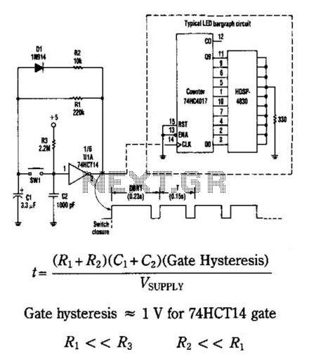
This circuit generates an output pulse when the pushbutton SW1 is pressed. It also functions as a hysteresis gate oscillator. Diode D1 and resistor R2 introduce asymmetry into the circuit. The delay before repeat time (DBRT) is influenced by...

This radio was purchased on eBay as non-functional and is missing all tubes and tube shields. It is a relatively rare Philco model, a 32-volt farm radio. Most 32-volt radios are from manufacturers like Delco, Silvertone, Coronado (Wells-Gardner), Parmak,...
This is a small circuit that provides extra security for radio controlled models. When the signal from the transmitter fails, grab the circuit and set the servo connected to a preset position. The circuit is built around a CMOS...
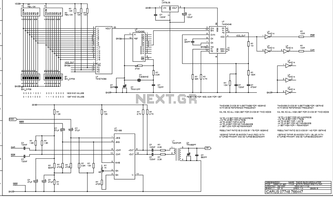
This document describes the transmitter system supplied to Radio Glen for testing as designed and constructed by Henry. The transmitter is supplied in prototype form and has the physical limitations of an instrument constructed using prototyping techniques. The transmitter...
Warning: include(partials/cookie-banner.php): Failed to open stream: Permission denied in /var/www/html/nextgr/view-circuit.php on line 713
Warning: include(): Failed opening 'partials/cookie-banner.php' for inclusion (include_path='.:/usr/share/php') in /var/www/html/nextgr/view-circuit.php on line 713