
Schematic Diagram Anti Theft Car wireless alarm
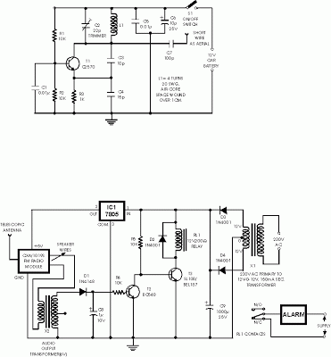
The Anti-Theft Car Wireless Alarm system is designed to enhance vehicle security through a wireless FM communication protocol. The system consists of a transmitter and a receiver, where the transmitter is installed within the vehicle and operates within a voltage range of 6 to 12 volts DC. The transmitter continuously sends signals to the receiver, which is tuned to the same frequency, ensuring seamless communication between the two components.
The use of the CXA1019 FM radio module as the receiver allows for a compact and cost-effective solution. The absence of noise at the output of the receiver when the transmitter is active indicates a stable connection, allowing for the normal operation of the relay driver circuit. The relay driver, utilizing a BC548 transistor (T2), is pivotal in controlling the relay operation. When the system is in a secure state, the relay remains energized, preventing the alarm from sounding.
In the event of a security breach, such as an unauthorized attempt to move the vehicle, the disruption of the radio link triggers the generation of hissing noise by the FM radio module. This noise is critical as it activates the relay switching circuit, which is facilitated by an audio transformer that couples the AC signals. The rectification and filtering process performed by diode D1 and capacitor C8 converts the AC signals into a usable DC voltage, which in turn biases transistor T2 into conduction. This action effectively grounds the base of transistor T3, causing the relay to deactivate and subsequently triggering the alarm system.
The design incorporates fail-safes, ensuring that even if the transmitter is disconnected from its power source, the receiver continues to produce the hissing signal due to the lack of a carrier frequency. This feature guarantees that the alarm remains active, providing a robust defense against tampering. Overall, the Anti-Theft Car Wireless Alarm system is a reliable solution for vehicle security, combining simplicity with effective performance.This is anti theft alarm with wireless connectivity, called Anti Theft Car wireless alarm The FM radio-controlled anti- theft alarm can be used with any vehicle having 6- to 12-volt DC supply system. The mini VHF, FM transmitter is fitted in the vehicle at night when it is parked in the car porch or car park.
The receiver unit with CXA1019, a sing le IC-based FM radio module, which is freely available in the market at reasonable rate, is kept inside. Receiver is tuned to the transmitter`s frequency. When the transmitter is on and the signals are being received by FM radio receiver, no hissing noise is available at the output of receiver.
Thus transistor T2 (BC548) does not conduct. This results in the relay driver transistor T3 getting its forward base bias via 10k resistor R5 and the relay gets energised. When an intruder tries to drive the car and takes it a few metres away from the car porch, the radio link between the car (transmitter) and alarm (receiver) is broken.
As a result FM radio module gene-rates hissing noise. Hissing AC signals are coupled to relay switching circ- uit via audio transformer. These AC signals are rectified and filtered by diode D1 and capacitor C8, and the resulting positive DC voltage provides a forward bias to transistor T2. Thus transistor T2 conducts, and it pulls the base of relay driver transistor T3 to ground level. The relay thus gets de-activated and the alarm connected via N/C contacts of relay is switched on. If, by chance, the intruder finds out about the wireless alarm and disconnects the transmitter from battery, still remote alarm remains activated because in the absence of signal, the receiver continues to produce hissing noise at its output.
So the burglar alarm is fool-proof and highly reliable. 🔗 External reference
Related Circuits
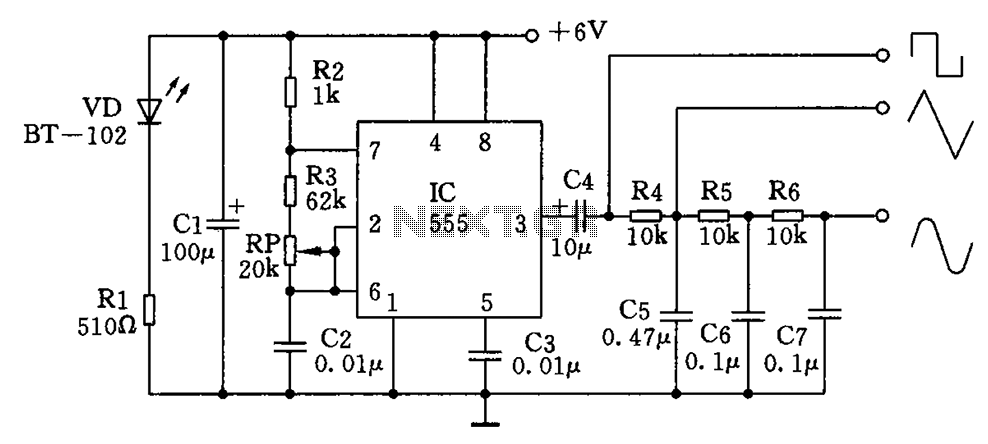
The circuit simultaneously generates a square wave, triangle wave, and sine wave, making it particularly suitable for electronics enthusiasts and students who wish to observe signal waveforms using an oscilloscope. This signal generator circuit is simple, low-cost, and allows...

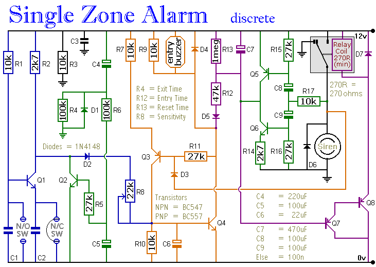
A CMOS 4060 burglar alarm circuit. This is a single-zone alarm with automatic exit, entry, and siren cut-off timers. It will accommodate all the usual types of normally-closed input devices, such as magnetic reed contacts. The CMOS 4060-based burglar alarm...
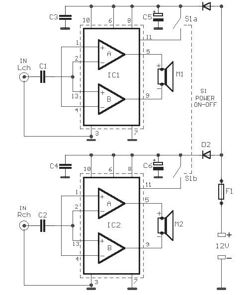
Car audio amplifier schematic diagram. Given the voltage of the car is +12 V, there is an opportunity to take power over a threshold. The solution involves using two amplifiers in a bridge connection, theoretically quadrupling the output power...
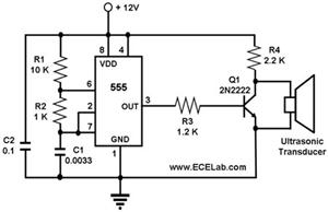
The ultrasonic cleaning machine functions as a humidifier and operates on a simple circuit primarily consisting of an ultrasonic oscillator. It generates ultrasonic frequency signals, typically within the range of 20-40 kHz, using a transistor. These signals are transmitted...
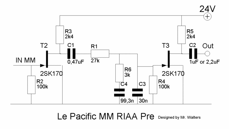
This document describes a DIY build of the Boozhound Laboratories JFET Phono Preamplifier constructed on a stripboard. The BHL preamp is primarily based on the Le Pacific RIAA phono preamplifier circuit. The construction utilizes brown polypropylene capacitors sourced from...
The circuit includes automatic exit and entry delays, a timed bell cut-off, and a system reset feature. It accommodates both normally-open and normally-closed switches, making it compatible with standard input devices such as pressure mats, magnetic reed contacts, foil...