
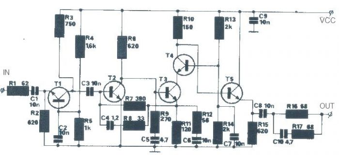
ultrasonic circuit diagram

The ultrasonic cleaning machine is designed to test the cleaning effects of ultrasonic technology, particularly for delicate components like computer motherboards. Manufacturers specializing in ultrasonic cleaning machines, such as those in Suzhou, have extensive experience in producing such devices along with drying equipment. A typical ultrasonic transmitter circuit operates at a frequency of 40 kHz, utilizing multiple oscillators to achieve stable output. The circuit includes components like capacitors and resistors to balance the waveform and ensure consistent performance.
The circuit is powered by a 9V battery and can operate with a current of approximately 25 mA. The transducer, designated T40-16, serves as the feedback coupling element in the circuit, generating ultrasonic signals that can reach distances greater than 8 meters. The oscillation frequency is determined by the characteristics of the T40-16 transducer, which resonates at 40 kHz, and the circuit is designed to maintain frequency stability without requiring adjustments. Inductive and capacitive components are incorporated for resonance tuning, ensuring that the system can adapt to a range of supply voltages between 3 to 12V.
The ultrasonic cleaning machine's circuit design includes four oscillators that work in conjunction with a gate drive function, allowing for controlled ultrasound radiation. This design enables efficient and effective cleaning processes, making it a valuable tool in various applications, including electronics and delicate components.Ultrasonic cleaning machine is a humidifier (do not believe you removed and see) circuit is very simple, just an ultrasonic oscillator! Ultrasonic frequency signal generated by the transistor (20-40Khz or so) received a transducer (piezoelectric buzzer in fact, the kind of copper on the card with speakers) principle is to make ultrasound a tiny impact on the object
surface deformation, to hit off the stains! Advantages: low cost, no cleaners, no-clean, used for final cleaning of printed circuit boards! Help me answer time of | I have to to the TA for helpParticipate in activities: No related content to participate in the activities of Huizhou, where the sale small ultrasonic cleaning machine ultrasonic cleaning machine how to test the cleaning effect of ultrasonic cleaning machines 1 home computer can be cleaned motherboard like objects NVC ultrasonic cleaning machines can work long summer ah Suzhou, specializing in the production of ultrasonic cleaning machines, drying equipment, the pipeline firms it More questions the same subject matter: ultrasonic cleaning machine schematic forwarded to: the promotion of choice for the new link up ultrasound ultrasound ultrasound # high quality Marine ultrasound company, specializing in the production of ultrasonic plastic welder, ultrasonic mask machines, ultrasonic cleaning machine. CE certification through the National Economic Ning Tianhua most professional ultrasonic cleaning machine Sky ultrasound R & D specializing in the production of ultrasonic cleaning machines, has 15 years of history, popular national telephone 40kHZ one ultrasonic transmitter circuit, the F1 ~ F3 three oscillators in the F3 is 40kHZ square wave output, frequency mainly by C1, R1 and RP decided to adjust the adjustable resistance with a frequency of RP.
F3 transducer excitation output T40-16 at one end and the inverter F4, F4 transducer excitation output T40-16 the other end, therefore, join F4 doubling the excitation voltage. Capacitors C3, C2 and F4 F3 balance the output of the waveform is stable. Inverter circuit, F1 ~ F4 with the CC4069 in four of six inverter inverter, and the remaining two do not (input should be grounded.
) Power Supply 9V laminated battery. F3 output frequency measurement should be 40kHZ 2kHZ, or should be adjusted RP. Transmitting ultrasonic signals greater than 8m. 40kHZ second ultrasonic transmitting circuit, the circuit transistors VT1, VT2 form strong feedback resonator oscillator, the oscillation frequency equal to the ultrasonic transducer T40-16 resonant frequency. T40-16 is the feedback coupling element, the circuit is the output for the transducer. T40-16 is similar at both ends of the square wave oscillation waveform, voltage amplitude close to the power supply voltage.
S is the power switch, S, T40-16 can drive a string of 40kHZ emitted ultrasonic signals. Circuit voltage of 9V, the operating current of about 25mA. Transmitting ultrasonic signals greater than 8m. Circuit can work without debugging. 40kHZ ultrasonic transmitter circuit, produced by the VT1, VT2 positive feedback form feedback oscillator. Circuit oscillation frequency depends on the feedback element of the T40-16, the resonant frequency of 40kHZ 2kHZ.
Frequency stability, no need to make any adjustment by the T40-16 as a transducer of the ultrasonic signals emitted 40kHZ. Inductor L1 and capacitor C2 for resonance tuning role played in the 40kHZ. Voltage of the circuit to adapt to a wide (3 ~ 12V), and the frequency change. Using fixed inductors, inductance 5. 1mH. Machine operating current of about 25mA. Transmitting ultrasonic signals greater than 8m. 40kHZ ultrasonic transmitter circuit of four, which consists of four complete and non-oscillation, and gate drive functions CC4011 by ultrasonic transducer T40-16 to control the receiver, the ultrasound radiation.
Which formed the door YF1 controlled oscillator with the d 🔗 External reference
Related Circuits
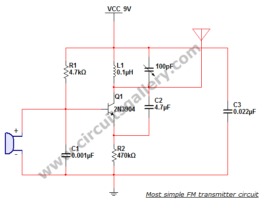
This is the simplest single transistor FM wireless transmitter circuit ever posted in CircuitsGallery. In the field of telecommunications, frequency modulation (FM) transmits information by altering the frequency of a carrier wave based on the message signal. FM utilizes...
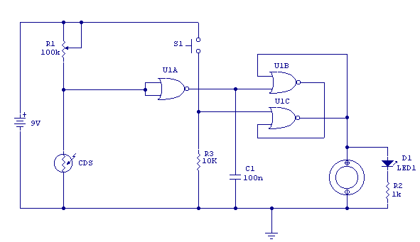
Variable resistor R1 adjusts the light threshold at which the circuit triggers. R1's value is chosen to match the photocell's resistance at darkness. The circuit uses a CMOS 4001 IC. Gate U1a acts as the trigger, U1b and c...
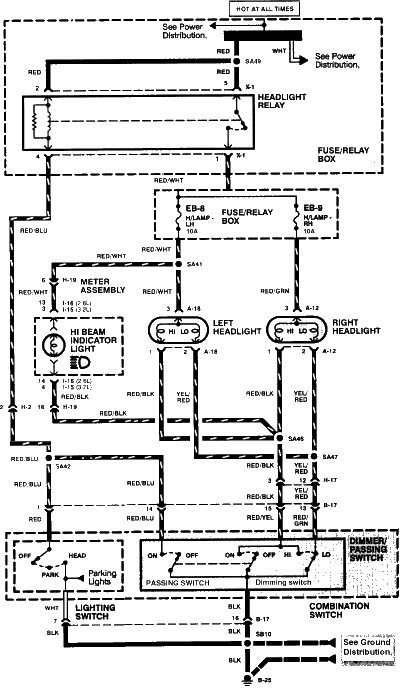
1996 Isuzu Rodeo Headlight Wiring Diagram. The 1996 Isuzu Rodeo headlight wiring diagram provides a detailed representation of the electrical connections and components involved in the vehicle's headlight system. This diagram is essential for understanding how the headlight assembly operates...
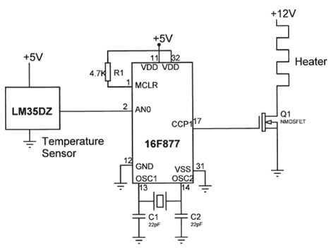
The electrical circuit diagram of this temperature control circuit consists of a 3-pin analog temperature sensor (LM35DZ), a built-in A/D converter microcontroller (PIC16F877), and the heater driver (IRL1004). The temperature control circuit utilizes the LM35DZ, a precision analog temperature sensor...
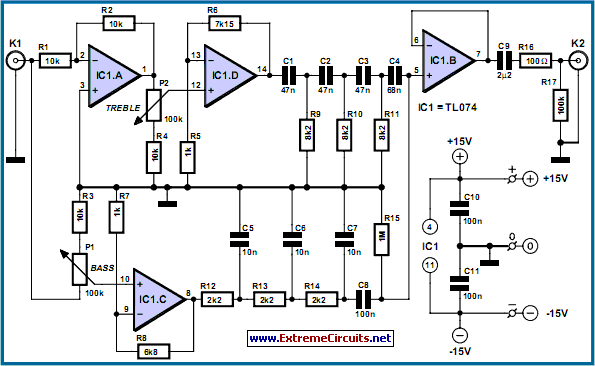
The paraphase configuration is noteworthy for its ability to adjust either treble or bass, but not both simultaneously. The adjustments made to the tone controls directly influence the slope of the frequency response and the extent of bass and...
The T1 transistor must be of the BF200 type (or a similar variant), while the other transistors can be of the BF214 type. To achieve high efficiency, the antenna amplifier should be positioned at a short distance from the...