
Need to have the circuit schematic for LG 29SA1RL model
The WS-55807 model's power-up issue requires a systematic approach to troubleshooting. The initial observation of the power button behavior suggests that the power supply circuit is attempting to initiate operation but is failing shortly thereafter. The identification of blown fuses F9A04 and F9A05 in the switched power supply regulator circuitry indicates a potential short or overload condition that may need addressing. The replacement of these fuses with 5A units and the subsequent power-up of the TV, albeit briefly, suggests that there may be other underlying issues in the power supply or convergence circuit that are causing excessive current draw.
The presence of a DM unit is typically crucial for the operation of many television models, particularly in managing power distribution and signal processing. Its absence in the WS-55807 model, as noted, may require further investigation into alternative components or modules that could be responsible for similar functions. The output resistors of IC8C02 should be closely examined, as their integrity is vital for the stability of the convergence circuit. If any resistors are found to be out of specification, they should be replaced to prevent damage to the Convergence ICs.
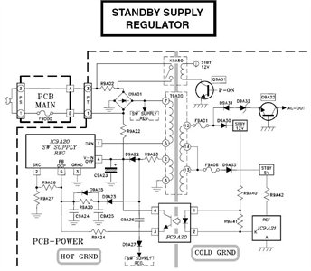
Lastly, the fusible return resistors should be tested individually to ensure they are functioning correctly. If any of these resistors are faulty, they could lead to excessive current draw and potential failure of associated circuitry. Careful attention to these components and their connections is essential in resolving the power-up issue of the WS-55807 model.The schematic is in PDF, and cannot be send to you by this site. Check this site. It has some schematics. Check whether the schematic you need is there. Pull up older posts there. I have a WS-55807 that will not power up. When the power button is pressed I hear a click from the back of the set, the timer light comes on and 3 seconds later I hear a click from the back of the set, and the timer light goes off. I started checking power to the unit with a voltmeter. For those intersted I have attached scematics: I verified that the PCB main fuse is good and there is 120V at point PT. From what I can tell is happening, the power button is pressed and the P-ON transistor is given a signal to conduct which causes K9A50 to close.
K9A50 opens after about 3 seconds. I am looking for other troubleshootinng steps. I have checked fuses F9A01 and F9A06, both are good. What are some other things to check for Where does the P-ON signal come from In the switched supplies regulator circuitry I found fuses F9A04 and F9A05 blown (denoted by red lines thru components). I jumpered around F9A04 and F9A05 with good 5A fuses and the TV powered on. However when the set was plugged into an outlet there was a huge power draw (sparks from the outlet).
After jumpering around the blown fuses, the TV stayed powered on for about 30 sec and then powered down. I pressed the power button a few more times and the same result. The TV stayed on for only 30 sec. Comment by TV_ITGuy, posted on Dec 19, 2007 Thanks for the advice ctf1800. I have read several posts that speak of the DM unit. I have looked in the back of my set and the DM unit is not in the location shown in the pictures. As I hope you can see in this picture, there is no DM unit to the far left, just open space. Also the service manual for the V17 chasiss does not speak of a DM module. I checked the reisitors on the output of IC8C02 which are a couple of 3. 9 ohm resistors in parallel. When I test them I get approximately 1. 9 ohms, which is what it should be with them being in parallel. Please let me know if I am off base on any of this. Thanks Comment by TV_ITGuy, posted on Dec 19, 2007 Also, I have replaced both of the Convergence IC`s when I replaced the fuses and diode.
first off you should replace both convergance IC and check the resisters coming off the output if any of the resisters are bad it will trash the ic on trying to power up. Comment by ctf1800, posted on Dec 20, 2007 there are six fusible return resistors ranging from 1. 5, 1. 8, 2. 2, 2. 7, 3. 3, 3. 9 Ohms. I would lift one side of the resister out. 🔗 External reference
Related Circuits
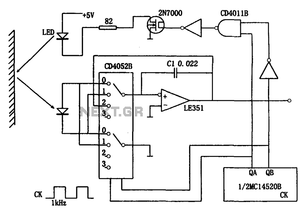
The circuit for detecting the intensity of reflected light includes infrared light-emitting diodes, photodiodes, CMOS analog switches, operational amplifiers, and other components. When the circuit operates, the infrared light-emitting diode (LED) initially remains off, allowing the photodiode to receive...
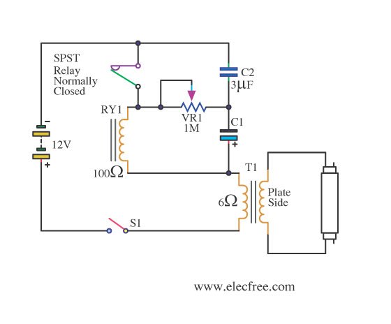
This is a flashing blink circuit designed for 12V applications. It utilizes a small-sized fluorescent lamp and operates through a relay that modifies the circuit from DC to AC. The flashing blink circuit operates at a voltage of 12V, making...
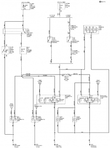
The connection and wiring between each part and component of the exterior lighting system of the vehicle includes elements such as the fusible link, junction block, tail light relay, cruise control, stop light switch, relay box, column switch, rear...
KA2211 is a dual audio power amplifier intended for consumer applications. It is designed to deliver high power with low dissipation and low noise. Additionally, it includes various protective features and is suitable for high-performance car audio applications. The KA2211...
The first BC109C transistor (on the left side) functions as a buffer, offering the circuit a high input impedance of approximately 250k ohms and a voltage gain slightly less than unity. As the Baxandall tone control circuit is a...
A composite pipe can be reduced to facilitate the adjustment of the control current within the tube. Composite pipes are often utilized in various applications due to their lightweight, strength, and flexibility. When discussing the reduction of a composite pipe,...