
Schematic Diagram VHF UHF Low-Noise amplifier circuit
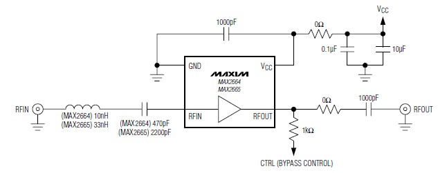
The circuit utilizes the MAX2664 and MAX2665 as the core components, which are designed to amplify weak radio frequency signals while minimizing noise. The MAX2664 is optimized for UHF applications, making it ideal for television and radio frequencies, while the MAX2665 is tailored for VHF applications, suitable for FM radio and other communication systems.
The low-noise amplifiers are configured in a common-source configuration, which provides significant voltage gain and a broad bandwidth. The integrated bypass switch allows the circuit to enter a low-power state when high signal levels are detected, effectively reducing power consumption during idle times. This feature is particularly beneficial in battery-operated devices where energy efficiency is critical.
External components required for the circuit are minimal, typically including a few resistors and capacitors for biasing and stability. The design can be easily integrated into compact PCB layouts, making it suitable for portable applications. The power supply requirements are flexible, allowing for operation from batteries or regulated power sources, which is advantageous for mobile devices.
The low current consumption of 3.3 mA ensures that the amplifiers can operate efficiently without significantly draining the battery, which is essential for devices such as smartphones and portable media players. The high gain of around 15 dB ensures that even weak signals can be amplified sufficiently for further processing, enhancing the overall performance of the system.
Overall, the MAX2664 and MAX2665 low-noise amplifiers present an effective solution for enhancing signal quality in VHF and UHF applications, making them a valuable addition to a wide range of electronic devices.A very simple low cost and ultra compact VHF UHF Low-Noise amplifiers circuit can be designed using the MAX2664 and MAX2665 ultra-compact LNAs for VHF/UHF applications. These devices incorporate a broadband LNA with an integrated bypass switch. The MAX2664 covers the UHF frequency range from 470MHz to 860MHz, and the MAX2665 covers the VHF frequen
cy range from 75MHz to 230MHz. Each device has a zero-power bypass mode for improved high-signal-level handling conditions. As you can see in the presented circuit diagram, this RF project requires very few external components. Both ICs has a high gain around 15dB and require a single power supply, that can provide an output voltage between 2.
4 to 3. 5 volts. VHF UHF Low-Noise amplifiers has a very low current consumption of 3. 3 mA and can be used in applications like: Smartphones/Handsets, MP3 Players, Home Audio/Video and other portable navigation devices. 🔗 External reference
Related Circuits
A regulator enables the powering of a 7.5-V cassette recorder or other devices from a 12-V DC automotive system. The circuit can provide approximately 600 mA of current. Q3 requires a heatsink due to its potential to dissipate up...
Expanding schematic circuit for the secondary circuit of high-voltage lines. The schematic circuit for the secondary circuit of high-voltage lines is designed to enhance the distribution and management of electrical power in high-voltage systems. This circuit typically includes components...
A simple Class B power amplifier can be constructed using the TDA8560 audio integrated circuit (IC). The TDA8560 amplifier features an internally fixed voltage gain, ensuring excellent channel balance. This audio amplifier project is capable of delivering dual 40-watt...
Early transmitters using LC oscillators experience significant frequency drift. The introduction of Surface Acoustic Wave (SAW) devices addresses this issue, providing substantial frequency stability comparable to crystals. These devices can achieve fundamental frequencies in the hundreds of megahertz or...
An FM transmitter circuit that utilizes a low power configuration, employing an operational amplifier as an audio preamplifier and a single transistor to function as the RF amplifier. This FM transmitter circuit is designed for low power applications, making...

This is an application circuit for calibration known as a high voltage AC calibrator circuit. An essential aspect of sine wave oscillator design is the stable control of amplitude. This circuit not only stabilizes the amplitude through servo control...