
Schematic effect
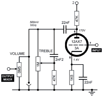
The mixer stage employs a common anode resistor, where the dry signal and delayed signal are combined to produce multiple repeats. Trimmer T2 adjusts the range of the LENGTH OF SWELL knob. The record amplifier is derived from tube section 6A, providing amplification and passive first-order filtering that results in a -6dB/octave roll-off of low and high frequencies before the grid. The bias oscillator circuit, based on tube section 6B, generates a 50KHz alternating current waveform that is mixed with the instrument signal and sent to the record head. The impedance of the heads used in the tube Echorec B2 models is approximately 650 ohms. Playback amplifiers utilize tube sections 1A, 1B, 2A, and 2B, enhancing the weak signal from the playback heads. A 220pF capacitor filters out the high-frequency bias signal from the audio output. Trimmer T5 functions as a tone control, while T4 serves as the output control for each of the four playback amplifiers.
The SELECTOR and SWITCH knobs constitute the switching circuitry. The SELECTOR knob facilitates the choice between ECHO, REPEAT, and SWELL settings. The ECHO setting produces a single distinct repeat, REPEAT generates multiple repetitions based on the LENGTH OF SWELL, and SWELL incorporates a slight signal from all four playback heads into the final mix, creating reverb-like effects. The REPEAT setting is particularly effective for achieving the early 1970s Pink Floyd delay effects. The 12-position SWITCH knob allows for the selection of different heads and combinations of heads for single and multi-tap delays. The Echorec schematics depict a simplified representation of the switch's function, and the Binson user manual does not clarify which head combinations can be selected. In theory, there are 24 (16) potential head combinations, including the option to select no heads. The output mixer buffer is configured as a cathode follower. Suggested modifications to enhance the high-frequency response include increasing the 47K resistor at the output to 100K and upgrading the 270nF output coupling capacitor to a polyester 680nF capacitor.The Echorec delay is a superb piece of engineering! In their quest for perfection Binson got many important aspects of the design right, maintaining a balance between simplicity and adding genuinely useful features to this classic echo machine. The engineers developed their own unique magnetic drum storage medium that offered superior reliability
(permanent guarantee`) and stability over 1/4 ³ tape used in all other tape echo units. No expense was spared in the design of the mixing and amplifier circuitry there are seven miniature B9A tubes inside the unit. All the tubes are still readily available 12AX7 and 12AU7 triodes. The level indicator is an EM81 tube which are also now being manufactured. This webpage contains a description of each functional part of the circuit, a flowchart clearly showing the signal flow, schematics for the Echorec IA and II.
The input buffer is an inverting gain stage based on section 4A of a 12AX7 tube. To optimize this to work with electric guitar pickups the the 47K resistor before the input coupling capacitor can be removed. Virtually all guitar amp input stages are direct coupled i. e. there is no capacitor. This is okay as a guitar pickup only generates an AC component with no DC offsets. Note: there is no cathode bias resistor. Typically triode amplifier configurations have a 1K8 resistor to maintain the grid voltage below the cathode.
Mixer stage with common anode resistor. This is where the dry` signal and delayed signal are mixed to create multiple repeats. Trimmer, T2 is used to set the range of the LENGTH OF SWELL` knob. The record amplifier is based on tube section 6A which provides some amplification. Additionally passive 1st order filtering before the grid provide -6dB/octave roll-off of low and high frequencies. The bias oscillator circuit is based around tube section 6B and generates a 50KHz alternating current waveform.
This is mixed with the instrument signal and applied to the record head. The impedance of the heads used in the tube Echorec B2 models is around 650 ©. The playback amplifiers are based on tube sections 1A, 1B, 2A and 2B, boosting the small signal from the playback heads. The 220pF capacitor filters out the HF bias signal from the audio signal. Trimmer, T5 is a tone control and T4 output control for each of the four playback amplifiers. The SELECTOR` and SWITCH` knobs form the switching circuitry. The SELECTOR knob allows selection between ECHO, REPEAT and SWELL settings. ECHO is just one distinct repeat; REPEAT is multiple repetitions, depending on the LENGTH OF SWELL`; SWELL introduces a little signal from all four playback heads into the final mix, to produce reverb type effects.
The REPEAT setting is the one` to use to create early 1970s Pink Floyd delay effects. The 12-position SWITCH` knob enables selection of different heads and combinations of heads for single and multi-tap delay. The Echorec schematics only show a simplified interpretation of the action of this switch and there is no explanation in the Binson user manual of which head combinations can be selected using the switch.
In theory there are 24 (16) possible head combinations (including the possibility of selecting no heads). The table below shows the actual combinations available with the 12-position selector switch: The output mixer buffer is a cathode follower configuration.
Suggested modifications to extend the H. F. response a little are to increase the 47K resistor on the output to 100K and increase the 270nF output coupling capacitor to a polyester 680nF 🔗 External reference
Related Circuits

The circuit produces a pleasing and accurate imitation of sound, making it suitable for sound effects such as doorbells. It generates a two-tone effect that closely resembles the sound of a cuckoo. This circuit is designed to create a two-tone...
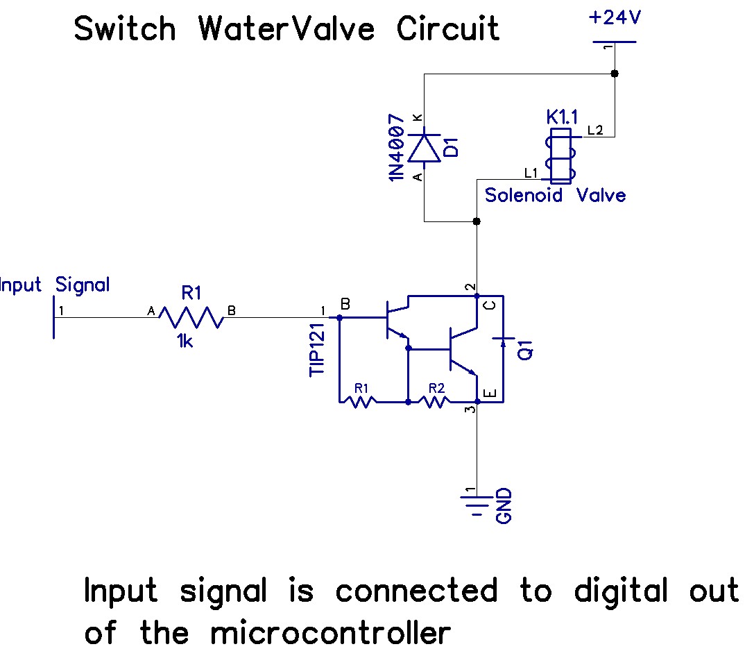
The Arduino Uno has adequate memory and ports, but efficient programming is necessary to store settings in memory. The Mega version offers increased memory and ports. The Shako valve operates on 24 volts DC; however, 12 volts is preferred...
This circuit turns off an amplifier or any other device when a low-level audio signal fed to its input is absent for at least 15 minutes. Pressing P1 switches the device on, supplying power to any appliance connected to...
The speaker protection circuitry is designed for independent operation of the left and right channels. The left channel is exemplified by components R2, C4, and the VT2, VT3 configuration, which includes a start delay circuit to prevent power surges...
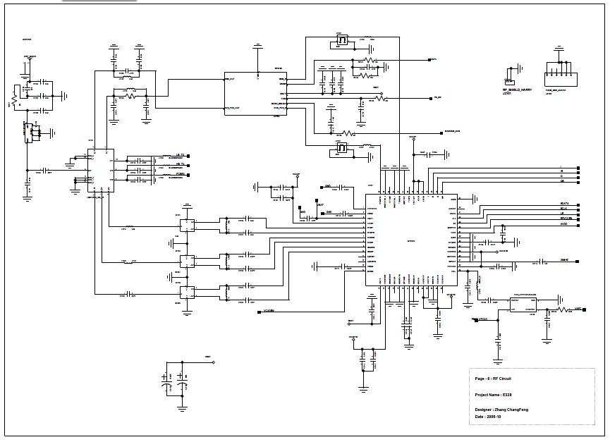
Analog baseband digital circuit table of contents: EMI interface, BPI bus, JTAG, LCD interface, keypad, UART, MINT, GPIO, MCP keypad, audio, RF, I/O connector, power cones, serial time, battery charging and analog, LED driver, RF control, JTAG, IOTA, audio...
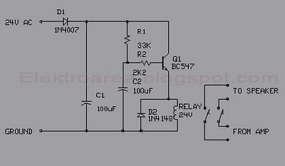
This circuit was designed for an audio amplifier project to control the speaker output relay. The primary function of this circuit is to manage the relay that activates the speaker output in the audio amplifier. The circuit introduces a...