
Two-channel speaker protection schematic

The speaker protection circuit is a critical component in audio systems, ensuring that speakers are shielded from potential damage caused by power surges or transients. The independent operation of the left and right channels allows for individual protection mechanisms, which is particularly beneficial in stereo setups.
The use of resistors R2 and C4 in conjunction with transistors VT2 and VT3 forms a delay circuit that effectively mitigates the risk of speaker damage during power-up. This delay ensures that the speakers remain disconnected from the power source until the circuit stabilizes, thus preventing any sudden inrush of current that could lead to speaker failure.
The choice of a high-brightness, two-color LED (µ3mm) serves both an aesthetic and functional purpose. The LED provides visual feedback regarding the circuit's status, indicating whether the system is operational. The adjustment of resistors R5 and R9 is crucial, as these components regulate the current flowing through the LED, ensuring it operates within its safe limits while also allowing for brightness variation.
The parallel configuration of the LED and the current limiting resistors with relays RE1 and RE2 is essential for protecting the circuit from voltage spikes. When the relays engage, they provide a pathway for the current, while simultaneously limiting the voltage that reaches the transistors. This configuration minimizes the risk of breakdown in critical components, such as VT2, VT3, VT5, and VT6, which are integral to the protection mechanism.
Selecting low-leakage tantalum capacitors for C4 and C9 is advisable due to their superior performance in maintaining stability and reliability in the circuit. These capacitors are less prone to leakage current, which can compromise the functionality of the protection circuit. Their use enhances the overall robustness of the speaker protection circuitry, ensuring that it operates effectively over time.
In summary, the speaker protection circuitry incorporates a well-designed arrangement of components that work together to safeguard speakers from power surges. The careful selection of components, along with the implementation of a delay circuit and protective measures against voltage spikes, contributes to the durability and reliability of audio systems. As shown for the speaker protection circuitry. It is designed for the left and right channels operate independently. The figure (to the left channel as an example) of R2, C4 an d VT2, VT3 composition start delay circuit to prevent power current shock speaker. Component selection: LED high brightness can be used µ3mm two-color LED. Since the LED current big and small, R5, R9 parameters may be slightly adjusted. At the same time, LED and current limiting resistor R5, R9 because in parallel relay RE1, RE2 ends, but also restrain the anti-peak voltage to prevent breakdown VT2, VT3 and VT5, VT6. C4, C9 best selection of low-leakage tantalum capacitors.
Related Circuits
Protect your valuable laptop against theft using this miniature alarm generator. Fixed inside the laptop case, it will sound a loud alarm when someone tries to take the laptop. This highly sensitive circuit uses a homemade tilt switch to...
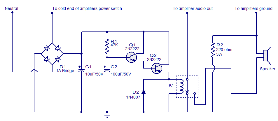
When the amplifier is powered on, the speaker experiences a sudden high voltage, resulting in a loud thud sound. This phenomenon is detrimental to the speaker and significantly shortens its lifespan. The circuit illustrated here connects the speaker to...
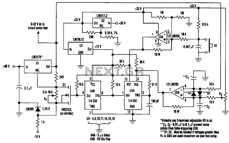
When testing a circuit, a variable voltage source with overvoltage shutdown capabilities is highly beneficial. In this circuit, resistor R1 is adjusted to a value 1 to 2 volts below the eventual shutdown threshold. Resistor R2 is responsible for...
This circuit generates a two-tone effect similar to the cuckoo song. It can be utilized for doorbells or other applications due to its integrated audio amplifier and loudspeaker. As a sound effect generator, it can connect to external amplifiers,...
PowerMan UPS/Inverters manufactures uninterruptible power supplies and voltage regulators. The business was founded in 1993 and was involved in distribution prior to the year 2000. PowerMan specializes in providing reliable power solutions, including uninterruptible power supplies (UPS) and voltage regulators,...
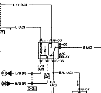
An automotive relay is being analyzed, which exhibits a more complex wiring configuration than typical relays. The diagram indicates that the B/G line maintains a high signal if certain conditions are met, specifically when the engine temperature is excessively...