
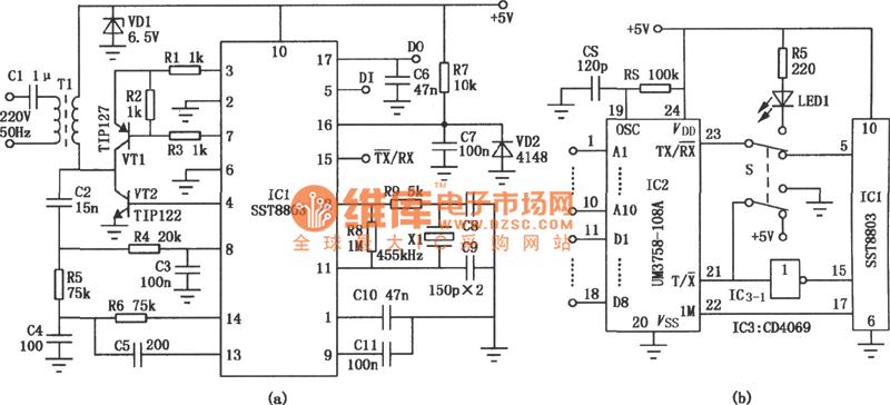
Schematic of The Infrared Rays Wireless Headphone
The inductive headphone system operates by creating a magnetic field that transmits audio signals to a receiver within the headphones. This setup requires a fixed installation of the transmitter, which restricts mobility and outdoor use. The transmitter typically consists of an oscillator circuit that generates a carrier frequency, which is then modulated with audio signals. The resulting magnetic field is picked up by the inductive receiver in the headphones, converting the magnetic signals back into audio.
In contrast, infrared wireless headphones utilize infrared light waves to transmit audio signals. The infrared transmitter can be positioned flexibly, allowing for a broader range of application, including outdoor settings where line-of-sight is maintained. The transmitter emits modulated infrared light, which is detected by a photodiode in the headphone receiver. This infrared communication provides a reliable audio link without the constraints imposed by physical installations required for inductive systems.
Both systems have their unique advantages and disadvantages. Inductive headphones are typically more secure from interference, as they operate on a principle that is less susceptible to environmental factors. However, the limitation of fixed installation makes them less versatile compared to infrared headphones, which offer greater flexibility and portability.Because of the transmitter circuit of the inductive headphone must installed on the room wall or on the ceiling, so the inductive headphone can not be used outdoor, this is the main weak point of the inductive headphone. But the infrared rays wireless headphone is not in this case, for the flexible infrared rays transmitter circuit, it can be used in electro..
🔗 External reference
Related Circuits

This digital thermometer circuit diagram utilizes a common 1N4148 diode as the temperature sensor. The diode's temperature coefficient of -2 mV/°C is leveraged to create an accurate electronic thermometer. A digital multimeter is employed to display the measured temperature,...

This circuit is a wireless car alarm system composed of two modules: a transmitter and a receiver. It operates using FM radio waves and is compatible with vehicles that have a 6-12V DC power supply. If the vehicle's power...

Many consumer electronic devices such as television sets, VCRs, CD players, and DVD players utilize infrared remote control technology. In certain situations, it is beneficial to extend the range of these remote controls. Infrared (IR) remote controls operate by emitting...
This circuit functions to monitor the duration of occupancy in a toilet, activating an alert if the time spent exceeds a predefined limit. The components involved include a resistor, integrated circuit (IC), capacitor, and transistor. The occupancy monitoring circuit is...

The following instructions outline the process for constructing a practical test tool designed for troubleshooting and analyzing digital and microcontroller circuits. The complete assembly and instruction manual can be downloaded from the provided web link: Don's Projects. To begin,...

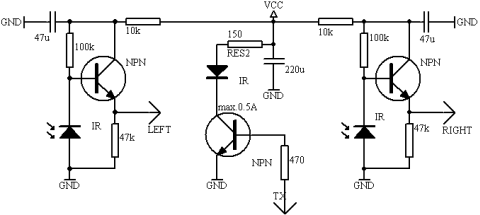
It is often necessary to control electrical appliances remotely, even when there is no direct line of sight between the transmitter and receiver. In modern electronic applications, remote control systems are increasingly utilized for various purposes, including home automation, industrial...