
Power Switch/Dimmer
The circuit design for this line voltage power controller incorporates a robust architecture that allows for precise control of AC loads via a DC input. The integration of a two-transistor pulse generator enhances the circuit's performance by ensuring rapid discharge of the timing capacitor, which is critical for eliminating hysteresis that can lead to inconsistent dimming behavior. This feature is particularly advantageous in applications requiring smooth and flicker-free operation, such as theatrical lighting or color organs.
The ability to adjust the brightness dynamically from one half-cycle to the next provides flexibility in controlling lighting effects, making it suitable for modern lighting systems that may be governed by a microcontroller. This adaptability is facilitated by the removal of the duty-cycle filter for applications requiring rapid adjustments, thereby allowing for real-time manipulation of the load's power.
The use of a diac optical isolator to trigger the triac ensures safe operation by providing electrical isolation between the high voltage AC load and the low voltage control circuitry. The design also accommodates variations in component values, enabling easy customization based on specific application requirements. The inclusion of provisions for snubber networks and line filters further enhances the circuit's reliability by mitigating potential electrical noise and harmonics that could interfere with other devices on the same power line.
Overall, this line voltage power controller circuit exemplifies a well-thought-out design that balances performance, flexibility, and reliability, making it an excellent choice for a wide range of AC load control applications.This line voltage power controller interfaces a DC control voltage or microprocessor logic output to an AC load. By adding a filter capacitor to the input resistors, the circuit may be controlled by a duty-cycle modulated square wave with about 2.
5 volts average giving minimum brightness and 3. 5 volts average giving full brightness. This circuit h as some distinct advantages over simpler "dimmers". The two-transistor pulse generator completely discharges the timing capacitor after each trigger pulse and before the next half-cycle begins, completely eliminating hysteresis and start-up problems. In dimmer mode, the circuit will readily start up at the dimmest setting without any overshoot or dead zone.
Since the pulse generator starts fresh at the beginning of each new half-cycle of the line voltage, the used could conceivably change the amount of each half-cycle applied to the load from one half-cycle to the next with a microcontroller synced to the line voltage. (The 10 uF duty-cycle filter shown in the schematic would be removed for such quick control. ) A simple on-off control is had by applying a logic signal to the input resistor but the velvet-smooth control in dimming mode makes flicker-free yet fast response possible for applications like color light shows (color organs), large pixel displays or smooth faders for sophisticated lighting systems.
The instant cycle-to-cycle response would be useful in feedback-type motor speed control applications, too. The schematic above features a diac optical isolator to trigger the triac but the single-polarity pulse is also suitable for driving a pulse transformer like the Vishay/Dale PT-50-102 or the Sprague 66Z906 as shown in the inset below.
A layout could accommodate both options. Ordinary 1/4 watt resistors are used throughout but the two pair of series 15k resistors could be replaced by single 30k, 1/2 watt resistors. The triac in the prototype is a T2800D (8 amp, 400 volt) but any number of types will work fine since the triac isolator provides a hefty trigger current pulse.
The prototype in the photo below includes a heatsink on the triac but the part runs cool with the relatively low power 60 watt bulb as a load. The dimmer is at a fairly low setting in the photo and a typical pulse transformer is shown right above the prototype board.
A 220 volt version is simply realized by increasing the two pairs of series 15k resistors up to a total of 60k each. Provisions for four 15k resistors in each spot would simplify parts procurement. Additionally, the 180 ohm in series with the diac optoisolator should be increased to 360 ohms. In lower power applications, the diac in the optoisolator could run the load directly. A layout could include provisions for a snubber network consisting of a series resistor and line voltage rated capacitor, typically 0.
1 uF. The board could also have provisions for a couple of line chokes or a common/differential mode transformer and another line voltage rated capacitor to form a line filter to prevent harmonics generated by the triac from getting back out on the line. These parts are not needed for most prototyping, however. The two 1N4003 rectifiers rectify the line voltage and provide a positive voltage to the two-transistor pulse circuit for each half-cycle of the line voltage.
As the voltage rises the 100 nF timing capacitor begins to charge through the 15k resistor and opto-isolator. (When the line voltage is sufficiently high, a bit of charging current also comes through the PNP base-emitter zener.
) When the voltage on the emitter of the PNP exceeds the voltage on the base, set by the two 330 k resistors, the transistor conducts. (Note that both voltages are increasing as the cycle proceeds but the emitter catches up to the base.
) The MPSA42 also conducts, reducing the voltage on the base of the 2N4403, causing the two transistors to snap on in a regenerative manner. The 100 nF c 🔗 External reference
Related Circuits
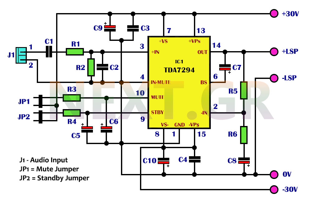
The integrated TDA7294 from SGS Thomson is a high-frequency acoustic power amplifier that boasts true high-precision specifications, making it suitable for various applications. Its standout feature is the significantly higher output power compared to typical amplifiers with similar distortion...
The LM317 is a versatile and efficient voltage regulator capable of delivering an output voltage range of 1.2V to 37V and a maximum current of 1.5A when used with an appropriate heat sink. This circuit is suitable for a...
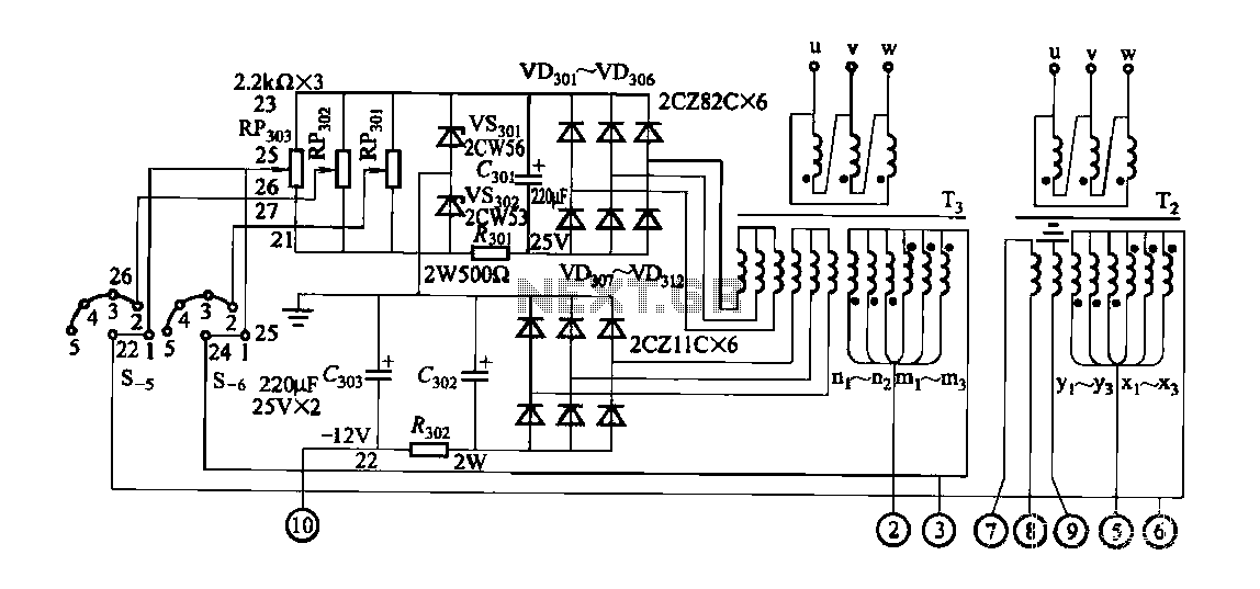
FGDF-3 is a three-phase low-temperature iron plating power supply circuit, while the KGDF-3 is a single-phase low-temperature iron plating power supply device that encompasses all the characteristics of the power supply unit. This design allows for an even distribution...
Quasi square wave resonant converters, also referred to as quasi resonant (QR) converters, facilitate the design of flyback Switch Mode Power Supplies (SMPS) with diminished Electro Magnetic Interference (EMI) and enhanced efficiency. Due to their low noise generation, QR...
USB Battery Charger for Lithium Ion batteries using the LM3622 is a specialized charger circuit designed to operate with power sourced from a USB connection. The current consumption of the LM3622 is limited to 400mA by a resistor (R1),...
This RS232 power supply circuit diagram is a simple RS-232 line driver power supply that operates from an input voltage as low as 4.2V and delivers an output of ±12V at ±40 mA with an efficiency of better than...
Warning: include(partials/cookie-banner.php): Failed to open stream: Permission denied in /var/www/html/nextgr/view-circuit.php on line 713
Warning: include(): Failed opening 'partials/cookie-banner.php' for inclusion (include_path='.:/usr/share/php') in /var/www/html/nextgr/view-circuit.php on line 713