
Schmitt Inverter
The Schmitt trigger circuit is crucial in digital electronics for signal conditioning, particularly in noisy environments. It provides a clean transition between high and low states, effectively eliminating false triggering due to noise or voltage fluctuations. The hysteresis effect ensures that once the input signal crosses the upper threshold, the output will remain high until the input drops below the lower threshold, thus providing a stable output.
In practical applications, Schmitt triggers are often used in waveform shaping, debouncing switches, and interfacing sensors with microcontrollers. The adaptability of the 74HC14 and similar devices to modify thresholds allows for tailored performance in various applications, accommodating different signal characteristics and improving reliability in digital systems. The ability to implement Schmitt triggers using both discrete components and integrated circuits provides versatility, making them essential components in modern electronic designs.The Schmitt trigger is a special circuit which acts like a switch that changes state at two different thresholds. These are called the upper and lower threshold or the positive and negative going threshold. The difference in these two threshold levels is called the hysteresis voltage. The Schmitt trigger does not react to any input voltage leve l in the range between the two thresholds, which for a 74C/HC14 corresponds precisely to the " forbidden zone ". A Schmitt trigger can also be likened to two comparators controlling an RS flip-flop at the output. In fact, the schematic of the 74C14 shows it to be designed that way. The upper threshold comparator sets the output latch and the lower threshold comparator resets the output latch.
Each of the six inverters in a 74C14 Schmitt trigger uses 12 MOSFETs, so by comparison the discrete version of the Schmitt trigger using 3 transistors and 11 other components is about as complex. Normally the 74HC14 threshold parameters are a fixed ratio of Vcc. This keeps the device functionally simple and as a result the 74HC14 Schmitt trigger is one of the most popular devices for interfacing real world signals to digital electronics.
It just doesn`t get any simpler compared to the other versions we will discuss. However it is a little known fact that it is possible to alter the thresholds of a 74HC14 by using negative feedback from output to input. For example, by adding a 5. 1M resistor from output to input and a 1M input resistor this will provide about 15% negative feedback.
That is subtracted from the internal 30% positive feedback and with Vcc =5V, it effectively changes the thresholds at the input of the 1M resistor to approximately 2. 1V and 2. 9V. Very useful if the signal of interest has smaller transistions than the normal 74HC14 hysteresis voltage.
Beside the 74HC14, there are a number of ways to implement a Schmitt trigger in CMOS logic. The simplest is to use a non-inverting buffer like the 74HC245 and connect a 3M resistor from output to input to provide positive feedback which is summed with the input signal through the 1M series resistor. These values will give the same thresholds as a 74HC14 but keep in mind the input resistance is 4M to GND or Vcc depending on the current output state.
The same circuit can be achived with two inverters like the 74HC240 version shown. The two inversions of the signal generate the required positive feedback. Both the true and inverted output signals are available. One variation on the last circuit is to add some negative feedback with a 4. 7M resistor from the inverted output to the input. This cancels out part of the positive feedback and reduces the hysteresis voltage while permitting a larger input resistor. Ideal amplifiers called opamps (a. k. a. , operational amplifiers ) can be used to make a simple (compared with the discrete version) Schmitt trigger but don`t let it lure you away from the object of the exercise showing just what goes on "under the hood" of a transistor Schmitt trigger: I have included the inverting and non-inverting examples of opamp Schmitt trigger which have adjustable threshold and hysteresis voltage.
Note that in both cases the potentiometers settings interact so that the threshold and hysteresis must be adjusted by trial and error. The above diagram reproduces the basic Schmitt trigger circuit of Richard Piotter. It consist of two inverters ( NPN and PNP ) which give a double inversion to the input signal. The output of the second stage is fed back and summed with the input signal and a resistor to ground.
Think of those resistors as forming a voltage divider which determines the input voltage required to cross the 0. 6 V threshold of the NPN base emitter junction to turn the transistor on of off. With the values given the positive going threshold is 1. 95 V and the negative going threshold is 1. 34 V assuming a Vcc of 5V. The output signal at the PNP c 🔗 External reference
Related Circuits
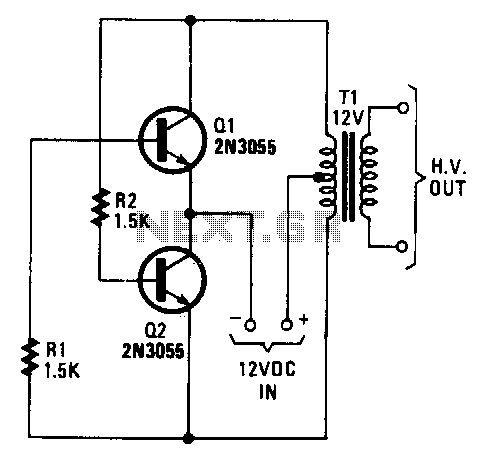
The transformer can be any 6.3 or 12.6 V type. Apply the 12-V DC input so the positive goes to the transformer's center tap and the negative goes to the two transistor emitters. Any bridge-type rectifier and filter can...
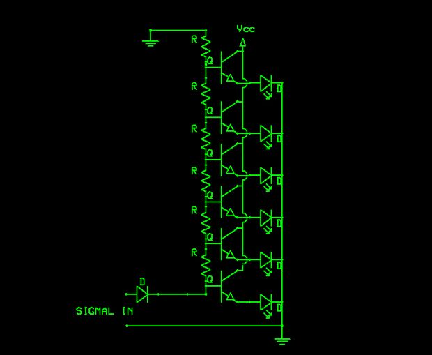
The schematic indicates that the input is routed through a voltage divider. This configuration is essential for the operation of the Schmitt triggers, which all activate under certain conditions. The voltage divider in the schematic serves to scale down the...
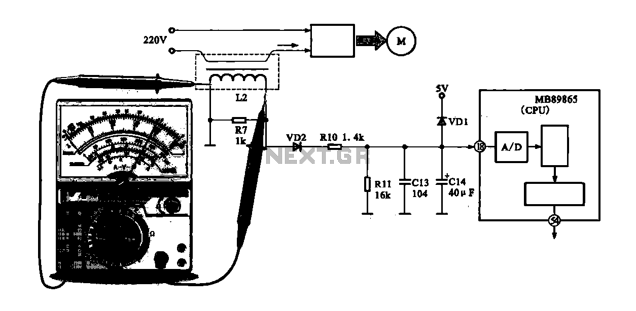
A current-voltage conversion circuit is commonly utilized in current detection applications. An example is the current detection circuit for a ring inverter air conditioner, which primarily serves to monitor the supply current of the compressor motor. Excessive current can...
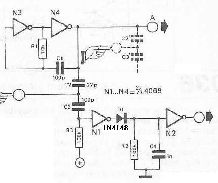
This touch sensor switch is designed using inverters (N1, N2) and several common electronic components. In the standby state, a signal is produced by the oscillator N3/N4 at the inputs of N1. When the touch sensor is activated, the...
The circuit samples the output of a multiplexer and provides the necessary current for driving a transfluxor in an analog-to-digital converter that generates a six-bit binary Gray code. -N. Aron and C. Granger, Analog-To-Digital Converter Uses Transfluxors, Electronics, 35:20,...
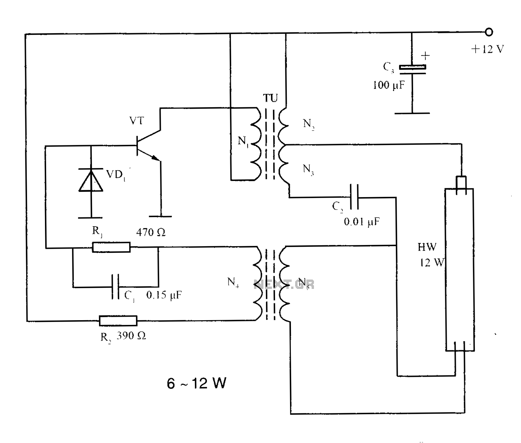
The lighting inverter circuit is designed for 6 to 12W fluorescent lamps. It operates by first bucking the mains voltage, followed by rectification and filtering to charge a battery. When the inverter is activated, it generates a high-frequency alternating...