
Schmitt trigger with programmable hysteresis
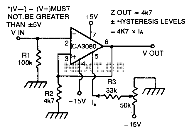
The CA 3088 is a dual operational amplifier that can be configured to function as a Schmitt trigger, which is a type of comparator circuit with hysteresis. Hysteresis is a property that prevents the circuit from responding to small fluctuations or noise in the input signal, thereby providing stable switching behavior. The hysteresis levels are defined by the feedback network, which typically includes resistors that determine the threshold voltages for switching.
In this configuration, Ia represents the output current from the amplifier, which flows through resistor R2 and impacts the feedback loop. The feedback network, composed of resistors R1 and R2, sets the upper and lower threshold voltages for the input signal. By adjusting R2, the designer can fine-tune the amount of hysteresis, allowing for greater control over the circuit's response to varying input conditions.
The symmetrical nature of the hysteresis levels about 0 V indicates that both the positive and negative thresholds are equidistant from the zero voltage level. This characteristic is beneficial in applications where balanced switching behavior is required, such as in digital signal processing or waveform shaping.
In practical applications, the CA 3088 Schmitt trigger can be employed in various circuits, including oscillators, timers, and pulse-width modulation systems. The ability to modify the hysteresis levels through Ia and the resistor values makes it a flexible choice for designing reliable and noise-immune electronic systems.CA 3088 is used as a versatile Schmitt trigger. The size of the hysteresis levels is determined by Ia that flows out of the amplifier"s output and through R2. Increasing Ia increases hysteresis and vice versa The positive and negative hysteresis levels are symmetrical about 0 V. 🔗 External reference
Related Circuits
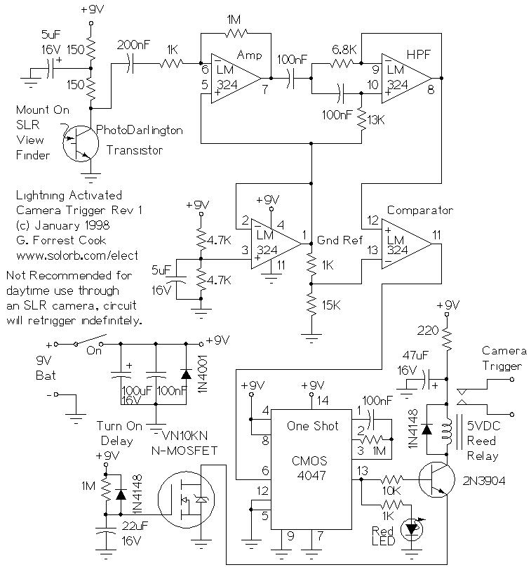
Lightning Activated Camera Shutter Trigger. This picture was taken using the circuit. This circuit is used to trigger a camera's electronic shutter circuit when a flash occurs. The Lightning Activated Camera Shutter Trigger is designed to capture images of lightning...
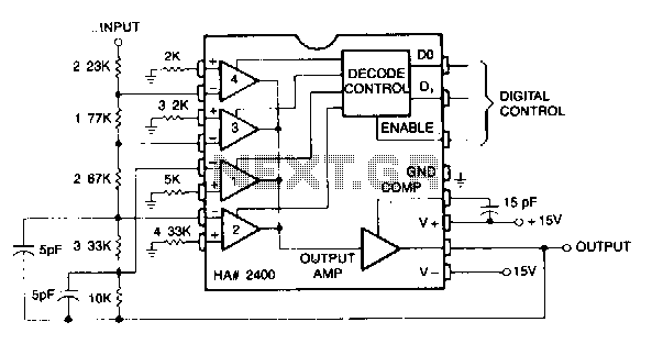
This circuit can be programmed for a gain of 0, -1, -2, -4, or -8. This could also be accomplished with one input resistor and one feedback resistor per channel in the conventional manner, but this would require eight...
The introduction for a unidirectional thyristor trigger circuit is also applicable to the TRIAC. Various configurations are presented in Figure 16-28. Figures 16-28 (a) and (b) illustrate a direct trigger circuit; Figure 16-28 (c) depicts a dual diode trigger...
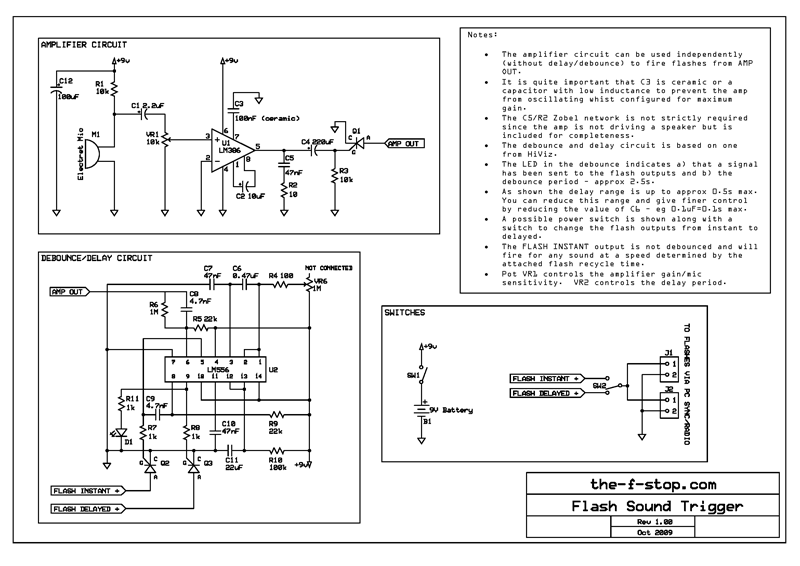
The following is a clear description of the final version of the trigger used and a circuit diagram for anyone wishing to construct their own. The initial version of this trigger was a simple single transistor amplifier, a piezo...
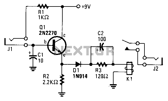
The transistor Q1 remains off until the magnetic switch connected to J1 closes. When this occurs, 9V is supplied through R1 to the base of Q1. As a result, Q1 turns on, which charges capacitor C2 through relay K1,...
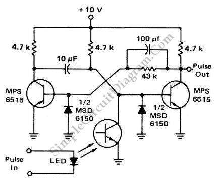
This is a flash-triggered (photo-driven) circuit that produces a pulse with a constant predetermined width. This circuit can be used to control any device. The flash-triggered circuit operates by utilizing a photodetector, which is typically a photodiode or phototransistor, to...