
Scoring Game circuit
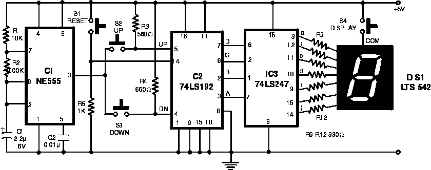
The circuit is designed to facilitate a simple scoring game for multiple players, utilizing a timer IC, two decade counters, and a 7-segment display driven by a BCD to 7-segment decoder/driver. The game operates on a 5V power supply, suitable for small-scale electronic projects.
The timer IC serves as the timing mechanism, ensuring precise counting intervals. The two decade counters, typically implemented using ICs such as the 4017 or 4026, are responsible for counting the scores. The forward counting is initiated by pressing switch S2, while pressing switch S3 causes the counter to decrement. A reset switch S1 is integrated into the design to initialize the game state before each round.
Upon pressing either scoring switch, the BCD outputs from the counters are updated rapidly, reflecting the current score. The last score remains latched at the output of the second counter IC (IC2) when the switch is released. This latched value is then fed into a BCD to 7-segment decoder/driver IC (IC3), which converts the binary-coded decimal to a format suitable for display on a common-anode 7-segment display (DIS1).
The operational sequence for players involves resetting the game using switch S1, followed by scoring with either S2 or S3, and finally reading the score by pressing switch S4. This approach ensures that players can keep track of their scores manually. The game continues until a player reaches or exceeds a score of 100 points, at which point they are declared the winner.
The physical assembly of the circuit can be accomplished on a multipurpose board, with the 7-segment display and other components mounted on a cabinet for visibility and accessibility. The use of tactile switches for input allows for reliable interaction during gameplay, while the overall design is straightforward, making it suitable for educational purposes or hobbyist projects in electronics.You can play this game alone or with your friends. The circuit comprises a timer IC, two decade counters and a display driver along with a 7-segment display. The game is simple. As stated above, it is a scoring game and the competitor who scores 100 points rapidly (in short steps) is the winner.
For scoring, one has the option of pressing either switch S2 or S3. Switch S2, when pressed, makes the counter count in the forward direction, while switch S3 helps to count downwards. Before starting a fresh game, and for that matter even a fresh move, you must press switch S1 to reset the circuit.
Thereafter, press any of the two switches, i.e. S2 or S3. On pressing switch S2 or S3, the counters BCD outputs change very rapidly and when you release the switch, the last number remains latched at the output of IC2. The latched BCD number is input to BCD to 7-segment decoder/driver IC3 which drives a common-anode display DIS1. However, you can read this number only when you press switch S4. The sequence of operations for playing the game between, say two players X and Y, is summarised below: 1.
Player X starts by momentary pressing of reset switch S1 followed by pressing and releasing of either switch S2 or S3. Thereafter he presses switch S4 to read the display (score) and notes down this number (say X1) manually.
2. Player Y also starts by momentary pressing of switch S1 followed by pressing of switch S2 or S3 and then notes down his score (say Y1), after pressing switch S4, exactly in the same fashion as done by the first player. 3. Player X again presses switch S1 and repeats the steps shown in step 1 above and notes down his new score (say, X2).
He adds up this score to his previous score. The same procedure is repeated by player Y in his turn. 4. The game carries on until the score attained by one of the two players totals up to or exceeds 100, to be declared as the winner. Several players can participate in this game, with each getting a chance to score during his own turn.
The assembly can be done using a multipurpose board. Fix the display (LEDs and 7-segment display) on top of the cabinet along with the three switches. The supply voltage for the circuit is 5V 🔗 External reference
Related Circuits
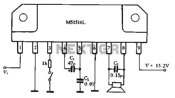
Figure 1-44 illustrates a dedicated BTL (Bridge-Tied Load) amplifier circuit, which consists of two single amplifiers. The relevant components are integrated into the circuit, simplifying the connections. The circuit operates at a power supply voltage of 13.2V and can...
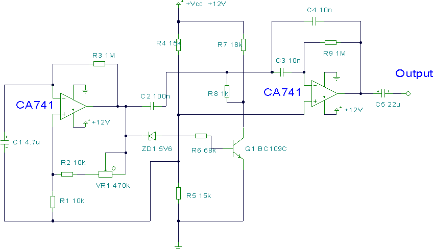
This circuit utilizes two operational amplifiers (op-amps) to create a unique sound effect. The first op-amp, CA741, is configured as a standard astable multivibrator, generating timing pulses controlled by components C1, R2, and variable resistor VR1. The output from...
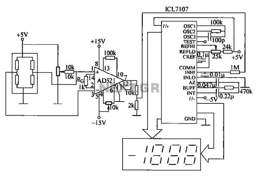
A pressure sensor circuit features a pressure sensor with a nominal resistance of 120 ohms. The amplifier circuit utilizes an AD521 operational amplifier with a gain of 100. It includes resistor components Rs and Rc, along with a decision-making...
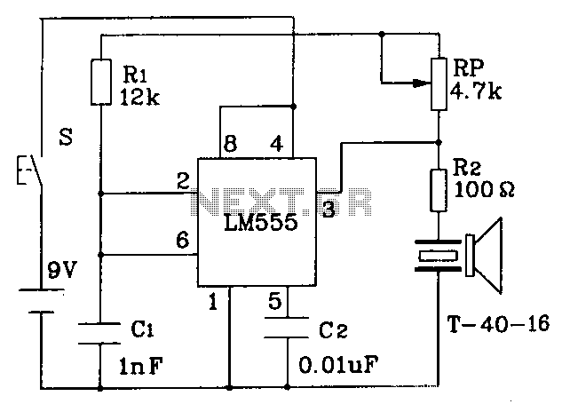
The circuit operates at a distance of 3 feet from the oscillating pulse output of a 555 timer generating a 40kHz signal, driving a T-40-16 transducer to emit ultrasonic signals at the same frequency. The circuit is powered by...
To replace a microphone with a 3.5" audio jack in a circuit, modifications will be necessary. The circuit currently utilizes an electret microphone, and adjustments must be made to accommodate the audio jack for audio transmission. The audio jack...
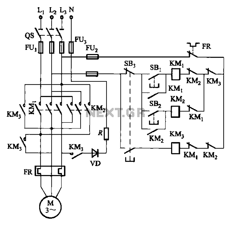
The circuit illustrated in Figure 3-145 employs a rectifier diode brake for neutral grounding in a three-phase, four-wire power supply system. This circuit design incorporates a rectifier diode brake, which plays a crucial role in ensuring the safety and reliability of...