
Forward and reverse operation of the dynamic braking circuit 2
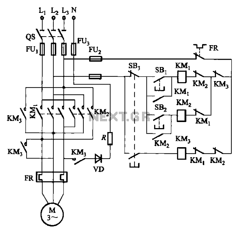
This circuit design incorporates a rectifier diode brake, which plays a crucial role in ensuring the safety and reliability of a three-phase power supply system. The primary function of the rectifier diode is to convert alternating current (AC) from the power supply into direct current (DC), which is essential for maintaining a stable voltage level and preventing fluctuations that could damage connected equipment.
In a three-phase, four-wire system, the neutral wire serves as a return path for unbalanced loads, allowing for the effective distribution of power across the three phases. The rectifier diode brake is strategically connected to the neutral point to ground the system, which helps in stabilizing the voltage levels and provides a reference point for the system. This grounding mechanism is vital for protecting the circuit from overvoltage conditions and ensuring that any fault currents are safely diverted to the ground, thereby minimizing the risk of electrical shock or equipment damage.
The circuit's configuration may include additional components such as capacitors for filtering, resistors for current limiting, and possibly fuses for overcurrent protection. These elements work in conjunction to enhance the overall performance and safety of the power supply system. Proper sizing and rating of the rectifier diode are essential to handle the expected load currents and to ensure efficient operation without overheating or failure.
Overall, the implementation of a rectifier diode brake in a three-phase, four-wire power supply system is a critical aspect of electrical engineering that contributes to the efficient and safe operation of industrial and commercial electrical systems.1The circuit shown in Figure 3-145. The line uses a rectifier diode rectifier brake for neutral grounding of the three-phase four-wire power supply system.
Related Circuits
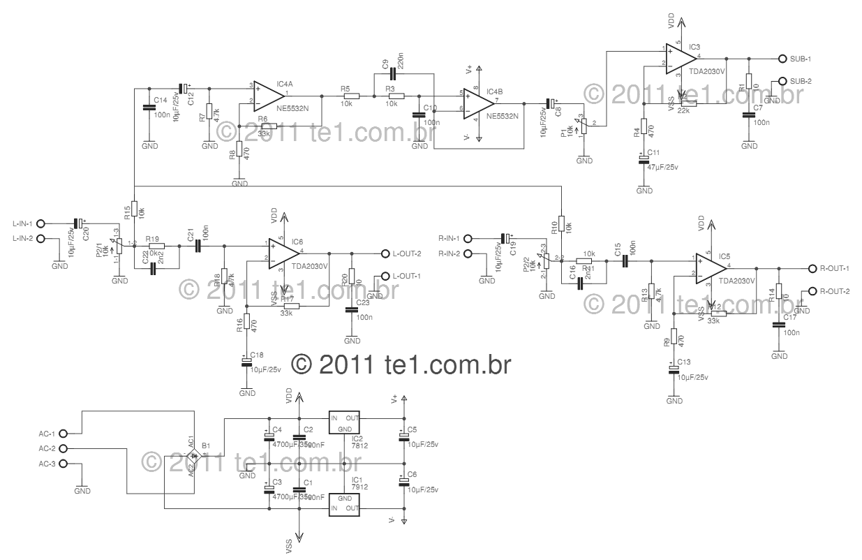
This circuit is a complete application for a 2.1 amplifier system, consisting of two satellite speakers powered by a TDA2030 and one subwoofer. This 2.1 system is commonly utilized in commercial applications as an amplifier for computers, enhancing audio...
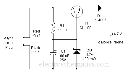
A mobile phone can be charged using the USB outlet of a PC. This simple USB cellphone charger circuit provides a regulated output of 4.7 volts for charging the mobile phone. The USB outlet typically supplies 5 volts DC...
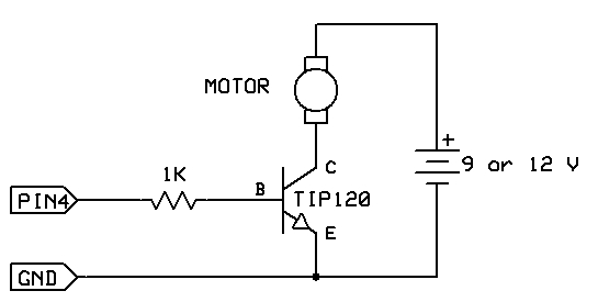
The strategy involves assembling the circuit in stages, testing each component as it is integrated. Once all connections are established and can be controlled or read correctly by the computer, the main program can be developed with assurance that...
This LED flasher circuit is a classic two-transistor flip-flop. It is a popular circuit often built by beginners in the electronics hobby. The schematic diagram of this well-known LED flasher circuit includes two transistors, two capacitors, four resistors, and...
This is a transistor inverter circuit diagram rated for 100 watts, designed as an easy-to-build circuit. It utilizes only transistors and does not incorporate any integrated circuits. The circuit converts a 12V battery input to a 220V, 50Hz square...

This circuit is designed to measure the inductance of an inductor labeled LX. The output of the circuit generates a TTL square wave, with its frequency being directly related to the inductance being measured. The output from the inductance...
Warning: include(partials/cookie-banner.php): Failed to open stream: Permission denied in /var/www/html/nextgr/view-circuit.php on line 713
Warning: include(): Failed opening 'partials/cookie-banner.php' for inclusion (include_path='.:/usr/share/php') in /var/www/html/nextgr/view-circuit.php on line 713