
60Hz Square-Wave Generator Circuit
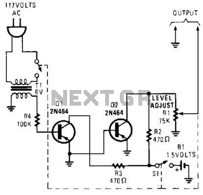
The generator circuit operates by leveraging an overdriven amplifier configuration, which is capable of producing a square wave output. The input to the circuit is derived from the standard 60 Hz AC line voltage, which is a common frequency for electrical power distribution in many regions. The overdriven amplifier takes this input and amplifies it beyond its linear operational range, resulting in a clipped output that approximates a square wave.
In practical applications, this square wave output can serve as a reliable clock source for various digital circuits, timing devices, and synchronous systems. The circuit may include additional components such as resistors and capacitors to stabilize the output waveform and improve its characteristics, ensuring that the square wave maintains its desired frequency and amplitude.
It is important to note that the performance of the circuit can be affected by external factors such as load impedance and power supply variations. Therefore, careful design considerations should be taken into account to ensure the circuit operates effectively in the intended application. Overall, this generator circuit is a versatile solution for generating clock signals in line-operated electronic systems. This generator circuit uses an overdriven amplifier to produce a 60-1 Iz square wave from the 60-Hz ac line. The circuit can be used in line- operated applications as a clock source. 🔗 External reference
Related Circuits
The following circuit illustrates the sensor circuit diagram for automatic room lights. This circuit is based on the CD4017 integrated circuit (IC) and features the use of two light-dependent resistors (LDRs). The automatic room light circuit utilizes the CD4017 decade...
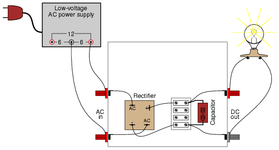
A bridge rectifier module is strongly recommended over building a bridge rectifier circuit using individual diodes. These modules are designed to be mounted on a metal heat sink. A metal enclosure is preferred over a plastic one due to...
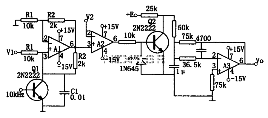
As illustrated in the dividing circuit diagram, A1 consists of a voltage-controlled current source, A2 functions as a voltage comparator, and A3 is configured as an active low-pass filter. When the time constant R1C1 is equal to the clock...

A Field Effect Transistor (FET) is an amplifying device where the output current is influenced by the input voltage. The FET preamplifier described here is sensitive. The Field Effect Transistor (FET) operates by utilizing an electric field to control the...
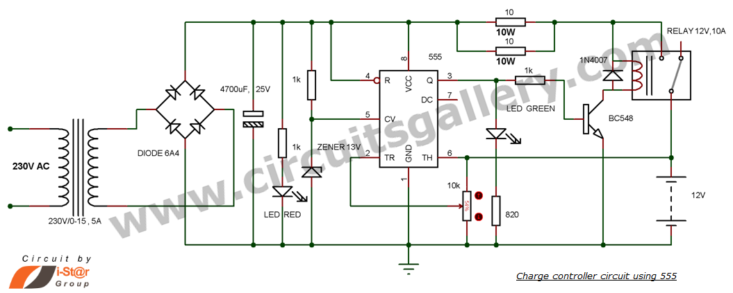
This is a simple DIY charge controller schematic created in response to a request from one of the readers on our Facebook page. The primary component of this automatic battery charger circuit is a 555 timer, which compares the...
This is a basic 555 square wave oscillator designed to generate a 1 kHz tone for an 8-ohm speaker. In the circuit, the speaker is isolated from the oscillator by an NPN medium power transistor, which supplies more current...