
USB Printer Chooser Switch
More: I used a pair of transistors to "OR" the Vbus voltage from the two cables that go to the computers, but a while after building it, I realised that the "off" transistor could turn on because the backwards transistor (collector and emitter swapped) could still work, but with most transistor types with a lower gain. Modifications to prevent the "off" transistor from turning on would have resulted in a lot of parts, so, about two years after building the switch, I tried a pair of Schottky diodes as David Hogg, a reader of this web site.
I used 1 Amp diodes instead of the lower current diodes because it will stand up better to abuse, and the 1 Amp diodes will have a lower voltage drop than one with a lower current rating at a given current. The diodes work just fine in my office.
While on this subject, a fellow by the name of Jim Glasgow built a switch before he came across this web site. His switch used a four pole break-before-make switch. I think this is a superior method, if you can find such a switch. One possible hitch to switching the ground is that there is no way to be sure that the ground connects first, so the data or Vbus conductors could connect first, thereby possibly subjecting the circuits in the printer or one of the computers to hazardous voltages. It's best to tie all the grounds together and only switch data and Vbus. The common admonishments apply to this circuit: Keep the wires as short as practical, make sure you don't have any shorts, and check operation before closing up the box. CONNECT THE SHIELDS FROM ALL OF THE CABLES TOGETHER. In the one I built, I did not use any sort of circuit board. I just wired the transistors and resistors to the conductors from the USB cables, using plenty of heat shrink tubing to keep things insulated. As soon as the circuit checked out in operation, I put the cover on the box.
The Lexmark printer is a USB 2.0 printer, and the USB ports on both of the late model computers are USB 2.0, but I doubt that communications were flying along at the blinding 480 Mbps High Speed data rate. More than likely, things are loafing along at 12 Mbps Full Speed data rate. That's my guess. The switch may work at 480 Mbps, but beyond keeping leads short, it may take some luck.
Now a word about this project. This is not a complete do-it-yourself project for the inexperienced. It is merely an example of what I did to solve a problem I had. The selection of the components used in this project depended mainly upon availability and convenience, and there are likely better choices. If you undertake this project, you may have different results. For example, if the cables are miswired, and your equipment is not grounded, there is a chance of damaging the printer, one of the computers, or all three. USB is well designed and robust, but it's not completely foolproof, especially in cases in which fool connect nonstandard equipment. Though this switch worked on my systems without a hitch, it may not work in your system. This project does not have an assembly diagram, printed circuit board artwork, or bill of material. You are responsible for any circuit you build. Before you start building, be sure you know what you are doing and the implications of any mistakes you might make.
The project involves a USB switching circuit utilizing a Double Pole Double Throw (DPDT) switch, which facilitates the connection of two computers to a single USB printer. The DPDT switch allows the user to alternate between two data lines (D+ and D-) while maintaining a common ground connection between the two systems. The design requires careful consideration of the USB standard, particularly regarding the VBus line, which is responsible for providing power to the peripheral device.
In this implementation, when switching between the two computers, the VBus line must be actively managed to ensure that the printer receives the necessary +5 Volts for operation. The initial approach involved using a pair of transistors configured to create an OR logic for the VBus voltage. However, it was later discovered that the configuration could lead to unintended activation of the "off" transistor due to reverse current flow. To mitigate this issue, the design was modified to incorporate Schottky diodes, which provide a low forward voltage drop and prevent reverse conduction.
The circuit emphasizes the importance of grounding; all shields from the USB cables should be connected together to minimize noise and potential ground loops. It is advisable to keep the wiring as short as possible to ensure signal integrity and reduce the risk of interference. The assembly of the circuit can be done without a printed circuit board, using heat shrink tubing for insulation and mechanical stability.
To enhance reliability, the circuit should be tested thoroughly before finalizing the assembly. It should be noted that while the circuit is designed to work with USB 2.0 specifications, actual data transfer rates may vary based on cable quality and overall design execution. Caution is advised when implementing this circuit, particularly for individuals with limited experience in electronics, as improper connections could lead to equipment damage. The project serves as a practical example of USB switching but does not provide detailed schematics or component lists, placing the responsibility of design and implementation on the builder.With a DPDT switch, I can switch the two data lines. I tried connecting the shields from the two computers together, the grounds two computers together, switching the D+ and D- lines with the DPDT switch, and leaving the VBus lines float, but for some reason it didn't work. The Lexmark printer seemed to need to see the +5 Volts. It had been many years since I read the USB standard (It was USB 1.0 back then) and I did not recall a function for the VBus beyond providing power to the peripheral, but in true experimentalist fashion, I added a transistor switch to supply VBus to the printer from whichever computer was connected, and the printer started working.
I used a pair of transistors to "OR" the Vbus voltage from the two cables that go to the computers, but a while after building it, I realised that the "off" transistor could turn on because the backwards transistor (collector and emitter swapped) could still work, but with most transistor types with a lower gain. Modifications to prevent the "off" transistor from turning on would have resulted in a lot of parts, so, abut two years after building the switch, I tried a pair of Schottky diodes as David Hogg, a reader of this web site.
I used 1 Amp diodes instead of the lower current diodes because it will stand up better to abuse, and the 1 Am diodes will have a lower voltage drop than one with a lower current rating at a given current. The diodes work just fine in my office. While on this subject, a fellow by the name of Jim Glasgow build a switch before he came across this web site.
His switch used a four pole break-before-make switch. I think this is a superior method, if you can find such a switch. One possible hitch to switching the ground, is that there is no way to be sure that the ground connects first, so the data or Vbus conductors could connect first, thereby possibly subjecting the circuits in the printer or one of the computers to hazardous voltages. Its best to tie all the grounds together and only switch data and Vbus. The common admonishments apply to this circuit: Keep the wires as short as practical, make sure you don't have any shorts, and check operation before closing up the box.
CONNECT THE SHIELDS FROM ALL OF THE CABLES TOGETHER. In the one I built, I did not use any sort of circuit board. I just wired the transistors and resistors to the conductors from the USB cables, using plenty of heat shrink tubing to keep things insulated. As soon as the circuit checked out in operation, I put the cover on the box. The Lexmark printer is a USB 2.0 printer, and the USB ports on both of the late model computers are USB 2.0, but I doubt that communications were flying along at the blinding 480 Mbps High Speed data rate.
More than likely, things are loafing along at 12 Mbps Full Speed data rate. That's my guess. The switch may work at 480 Mbps, but beyond keeping leads short, it may take some luck. Now a word about this project. This is not a complete do-it-yourself project for the inexperienced. It is merely an example of what I did to solve a problem I had. The selection of the components used in this project depended mainly upon availability and convenience, and there are likely better choices. If you undertake this project, you may have different results. For example, if the cables are miswired, and your equipment is not grounded, there is a chance of damaging the printer, one of the compuers, or all three.
USB is well designed and robust, but its not completely fool proof, especially in cases in which fool connect nonstandard equipment. Though this switch worked on my systems without a hitch, it may not work in your system. This project does not have an assembly diagram, printed circuit board artwork, or bill of material. You are responsible for any circuit you build. Before you start building, be sure you what you are doing and the implications of any mistakes you might make.
🔗 External reference
Related Circuits
The count switching circuit consists of an electronic switch and a pulse delay circuit for control. The count switching circuit is designed to manage the switching of signals in a controlled manner. The electronic switch serves as the primary component...
The circuit detects the mains current supplied to a master device and controls the on/off state of slave equipment. This functionality is particularly beneficial in environments such as hi-fi systems or home computers, where multiple peripheral devices can be...
This constant current constant voltage switched-mode power supply (SMPS) is designed for efficient battery charging. The circuit outputs a constant voltage of 7.2V and a constant current of 600mA. The operation mechanism is straightforward: when the load impedance is...
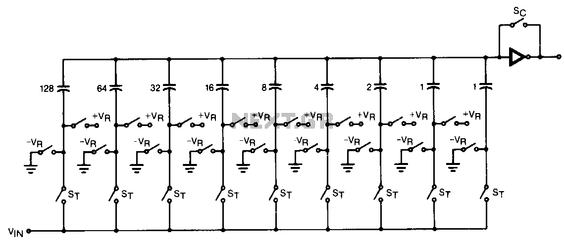
The CMOS comparator in the successive-approximation system determines each bit by examining the charge on a series of binary-weighted capacitors. In the first phase of the conversion process, the analog input is sampled by closing switch SC and all...
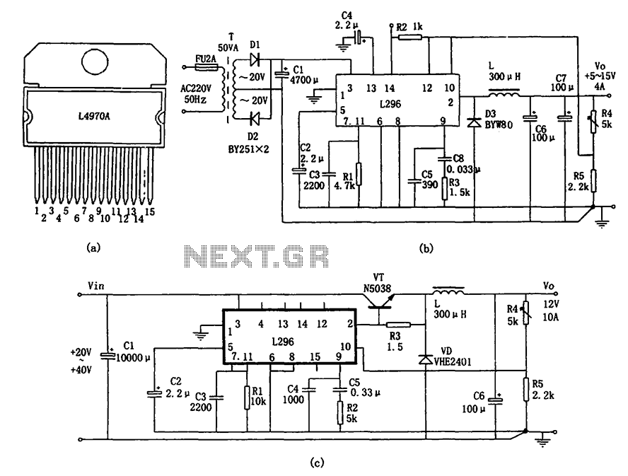
The L296 chip is a high-current switching power supply component designed to operate within a voltage range of 5 to 15V and provide an output current of up to 4A. This monolithic chip incorporates several features including enhanced protection...
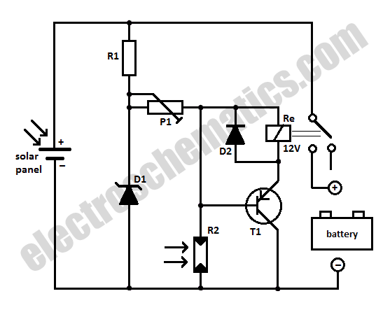
When charging a battery during the day using a solar panel, there is a risk of the battery partially discharging through the panel after sunset. This solar panel power switch circuit eliminates the need for a diode by utilizing...