
dark sensor relay switch lm741

The LM741 operational amplifier is utilized in this circuit as a voltage comparator. The LDR's resistance decreases with increasing light intensity, which alters the voltage across it. When the light level falls below a certain threshold, the voltage at the inverting input of the LM741 becomes lower than that at the non-inverting input, causing the output of the LM741 to switch from a low state to a high state. This transition activates the relay, allowing it to close the circuit and power an external device, such as a light or alarm.
In this configuration, a potentiometer may be included to fine-tune the reference voltage at the non-inverting input, providing adjustable sensitivity to light levels. The relay should be rated appropriately for the load it will control, ensuring safe operation. Additionally, a diode is typically placed in parallel with the relay coil to prevent back EMF from damaging the LM741 when the relay is de-energized.
Power supply considerations for the LM741 and the relay must also be addressed. The circuit can be powered using a standard DC supply, with appropriate voltage levels for both the operational amplifier and the relay. Proper decoupling capacitors should be included to stabilize the supply voltage and reduce noise, ensuring reliable operation of the circuit.
Overall, this LM741 dark sensor relay switch circuit serves as an effective solution for automated control in low-light conditions, with applications ranging from security systems to automatic lighting.Here is the project/schematic of LM741 dark sensor relay switch circuit. The circuit will activate the relay switch when there is no light on the surface of LDR.. 🔗 External reference
Related Circuits
4QD manufactures motor speed controllers, and all their H bridges utilize PWM. This is a simple switch circuit designed for reversing and stopping a motor without speed control. Two inputs, A and B, control the bridge. When both inputs...
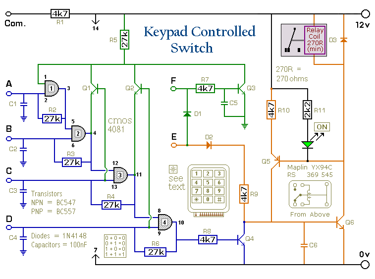
This is a universal version of the Four-Digit Alarm Keypad. The design of the output section has been modified to free up the relay contacts, allowing the circuit to function as a general-purpose switch. A single-pole changeover (SPCO) or...
This circuit converts the analog signal from the reversed LED, which is in sensing mode, and amplified by the operational amplifier, into a digital (on/off) signal. The original complex design has been simplified. An alternative approach is discussed in...

The objective is to investigate low RPM issues and gather expert opinions before proceeding with the disassembly of wire looms for tracing purposes. To address low RPM problems in an electronic system, it is essential to conduct a thorough analysis...
This document explains the adaptation of a standard 40 amp car relay, converting it from a "normally open" contact configuration to a "normally closed" contact configuration. While it is possible to perform this modification, automotive relays with "normally closed"...
The objective is to add a security sensor light near the main entrance that operates on 12 volts. While 12-volt PIR sensors are available, they tend to be costly, often exceeding $50 each and are specifically designed for security...