
Thyristor overcurrent protection circuit 2
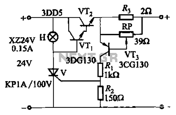
This circuit utilizes a thyristor for overcurrent protection, which is a crucial component in safeguarding electronic systems from damage due to excessive current. The thyristor operates by remaining in a conducting state until the current flowing through it falls below a certain threshold. In this configuration, transistors VTi and VT2 are employed to monitor the current level. When the current exceeds the predefined setpoint, the circuit triggers the thyristor to turn off, effectively disconnecting the load and preventing potential damage.
The inclusion of an adjustment potentiometer (RP) provides flexibility in setting the desired current threshold. This allows for customization based on the specific requirements of the application. The adjustment can be made by rotating the potentiometer, which modifies the resistance in the circuit, thus changing the voltage at the trigger input of the thyristor.
The indicator H serves as a visual alert, illuminating when an overcurrent condition has been detected. This feature is essential for operators to quickly identify issues within the system and take necessary actions to mitigate risks.
Overall, the circuit design emphasizes rapid response to overcurrent situations, ensuring that the electronic system remains protected while allowing for user-defined current settings through the adjustable potentiometer. The integration of these elements makes the circuit a reliable solution for managing current levels in various electronic applications.Adjusting Ro or RP, you can change over the current setpoint. Circuit shown in Figure 14-98. Overcurrent, V conduction thyristor, transistor VTi, VT2 off immediately cut off th e power play fast protection, the indicator H lights. Adjustment potentiometer RP, can change over the current setpoint.
Related Circuits
Artificial hatching or breeding of tropical fish requires the configuration of an oxygen pump and a circulating pump for the fish pond. Continuous operation of both pumps not only wastes energy but also risks damaging components. This example illustrates...
Create an oscillator circuit using an operational amplifier and a 7.68 MHz crystal. The design should be similar to the schematic provided below, but specifically tailored for a 7.68 MHz crystal. The available components include the crystal, various capacitors,...
The Motorola company's MC14440 CMOS integrated circuit is designed for timing and displaying calendar functions. It utilizes a 32.768 kHz NT cutting type quartz crystal along with fine-tune capacitance to generate time-based signals. The display circuit operates on a...
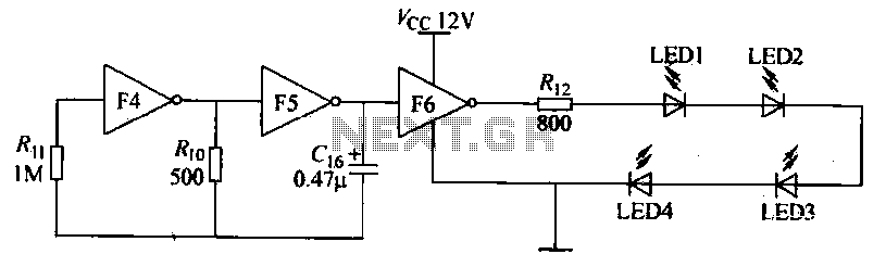
Gates F4, F5, and F6 together form a low-frequency oscillator that drives high-brightness light-emitting diode (LED) flashes. The light-emitting diodes may be arranged around the booth seat for decorative purposes. The automatic referral machine is used prior to operation...

The LA1070 is an automatic gain control integrated circuit designed for use with automotive on-glass antennas. It is produced by Sanyo Semiconductor Corporation. The LA1070 operates by automatically adjusting the gain of the antenna signal to maintain a consistent output...
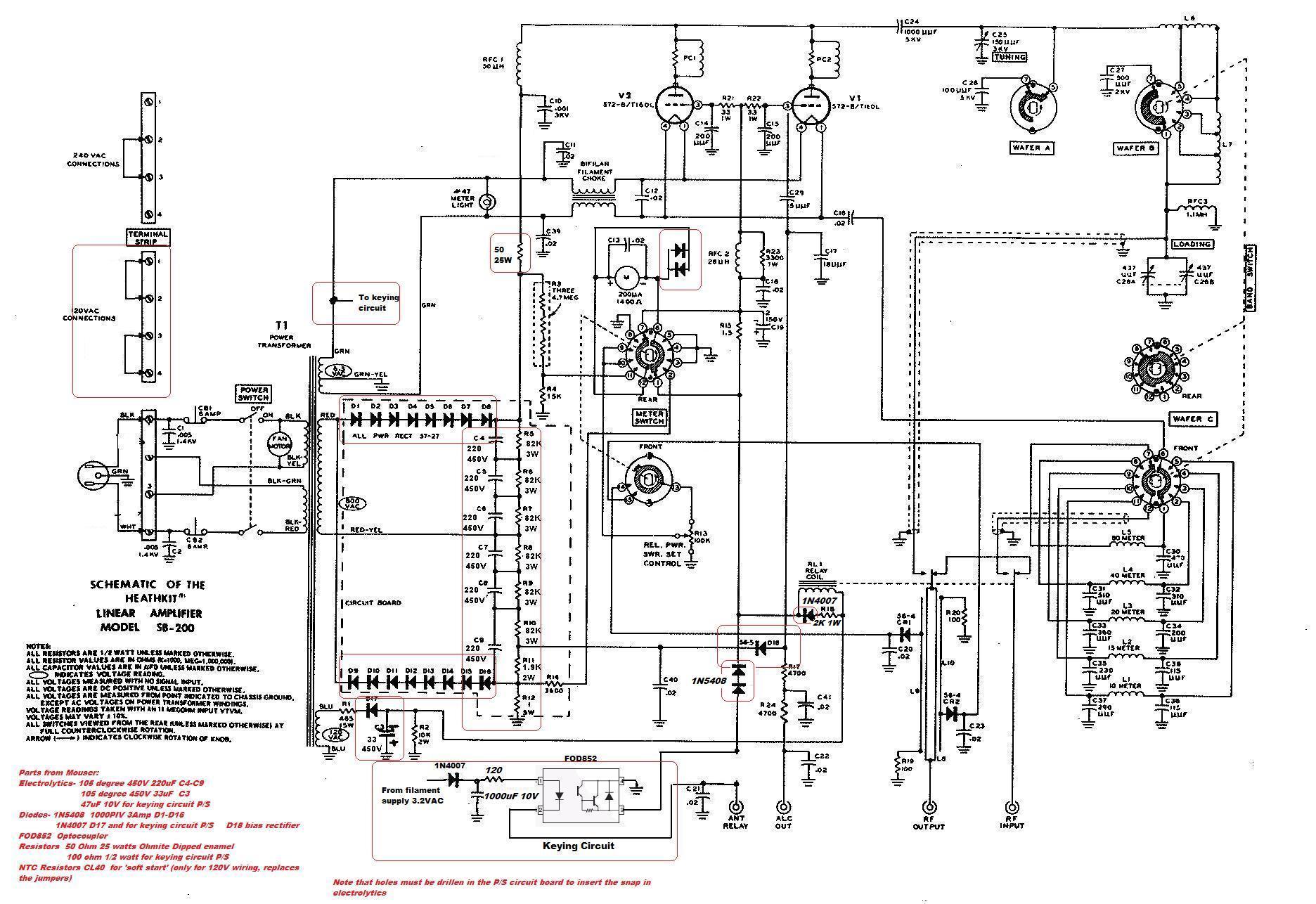
This circuit serves as a cost-effective alternative to commercially available keying circuits. It has been successfully implemented in the SB-200 amplifier. A schematic of the modified SB-200 is provided. The described circuit is designed to function as a keying mechanism...