
Secure lock circuit (CD4017) schematic
")
The described circuit employs the CD4017 decade counter IC, which is capable of counting from 0 to 10 and can be configured to produce outputs corresponding to each count. In this application, the CD4017 serves as the core component for the password entry system, where each key press corresponds to a specific output state.
The two CD4017 counters are connected in a manner that allows for the detection of a four-digit password. Each CD4017 counter outputs a high signal on its respective output pin when the count reaches a specific number. The password switch is implemented using a key switch mechanism that allows the user to input a sequence of digits. The logic combination of components ensures that only the correct sequence of key presses will activate the desired output.
The circuit design includes pull-down resistors to ensure stable logic levels at the inputs of the CD4017 counters. Additionally, debounce circuitry may be incorporated to prevent false triggering caused by mechanical bouncing of the key switches.
The output from the counters can be utilized to drive additional components, such as LEDs for visual feedback or relays for activating other devices upon successful password entry. The simplicity of the circuit makes it suitable for applications where basic access control is required, such as in security systems or electronic locks.
Overall, this password switch circuit demonstrates an effective use of the CD4017 decade counter in a straightforward electronic access control application.Circuit as shown by the two and four decimal counter CD4017 password switch composed by the output terminal of the key switch logic combination of components to another feature of the electronic code switch. Circuit is simple, and only two CD4017 four password input keys.
Related Circuits
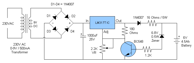
This article discusses a fully automatic 6V 4.5AH battery charger circuit that utilizes the LM317T integrated circuit along with a few additional components. The circuit is designed to charge a 6V lead-acid battery. The circuit utilizes the LM317T voltage regulator,...
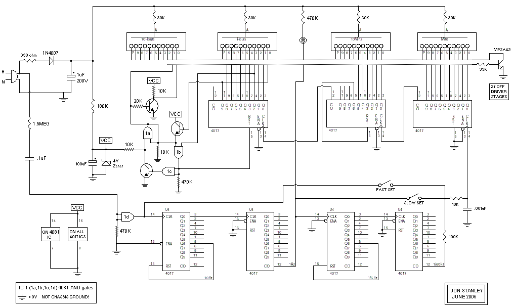
This is the new and improved nixie clock utilizing one of the smallest nixie tubes available, the Russian IN-17 nixies. The clock circuit is based on revisions of the version 1 nixie clock that were utilized in the Single...
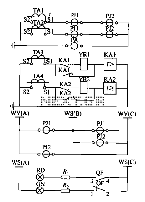
Expanding schematic circuit for the secondary circuit of high-voltage lines. The schematic circuit for the secondary circuit of high-voltage lines is designed to enhance the distribution and management of electrical power in high-voltage systems. This circuit typically includes components...
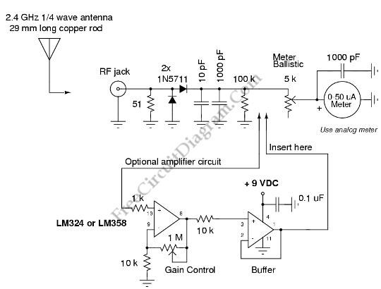
Field strength meters are essential tools for individuals working with radio transmitter electronics. The following is an example of a circuit that serves this purpose. A field strength meter circuit typically consists of several key components, including an antenna, a RF...
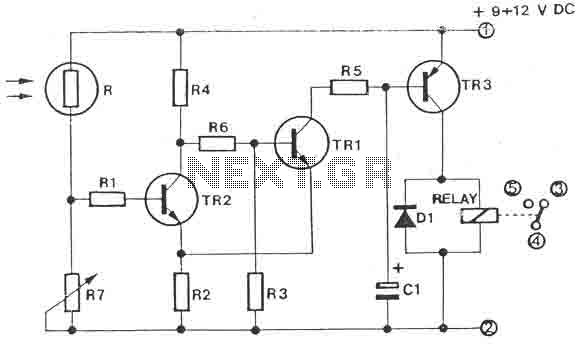
The circuit is a light switch that activates when the light intensity drops on a photoresistor. It features a straightforward construction and can be utilized in numerous applications. The photoresistor and the trimmer function as a voltage divider and...
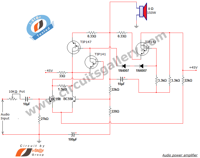
This document presents a new audio power amplifier schematic utilizing TIP darlington pair transistors. It is suitable for both home audio and car audio amplifiers. The TIP142 and TIP147 darlington pair transistors create a push-pull high-power amplifier configuration, while...