
Nixie Clock Version 2
The nixie clock design is characterized by its efficient use of space and components, making it suitable for compact applications. The 4081 quad 2-input AND chip plays a pivotal role in simplifying the logic design by reducing the number of discrete components required, thus enhancing reliability and minimizing potential points of failure. The configuration of the AND gates not only facilitates the counting mechanism but also ensures that the visual output is clear and distinct, with the use of transistors to control the high-voltage supply to the nixie tubes.
The choice of a half-wave rectifier circuit for powering the nixies is noteworthy, as it balances the need for high voltage with simplicity in design. The slight flickering effect, while unconventional, is a calculated decision aimed at prolonging the operational life of the nixie tubes, which are sensitive to prolonged high-voltage exposure. This design choice reflects a deep understanding of the operational characteristics of nixie tubes, optimizing their performance while also addressing longevity.
Overall, this nixie clock represents a blend of traditional technology with modern design principles, showcasing how classic components can be effectively integrated into a compact and functional timekeeping device. The addition of the colon indicator enhances the aesthetic appeal, making it not only a functional piece but also an attractive display item. This design can serve as a reference for further developments in nixie clock technology, particularly in the areas of compactness and energy efficiency.This is the new and improved nixie clock using one of the smallest nixies in the world, the Russian IN-17 nixies. The clock circuit is based on revisions of the version 1 nixie clock that were used in my Single Meter Clock.
The logic circuits of the clock is basically identical to the Single Meter Clock except it has SLOW and FAST set instead of h ours and minutes set. The only things that is unique to this version 2 clock compared to the version 1 is the 4081 quad 2-input AND chip, which eliminates the 4013 flip flop and the two 4017 counters. An AND gate is wired as a flip flop for the 10 hours, and when set, the "1" digit is lit. A transistor NOT gate is used for the "0" digit on the hours so when the AND gate is reset, the "0" is lit.
When the AND gate is set, the transistor is activated, which shuts off the Vcc from the HV transistor so the "0" turns off while the "1" comes on. The other AND gate was used to compare when the hours rolls over to 13 (from 12:59) to reset everything back to 1.
The remaining AND gates were used as buffers, one for the 60Hz line and another for the reset circuit. As a result of using the 4081 chip, I was able to stuff all of the logics and parts on a 3 by 4 inch board.
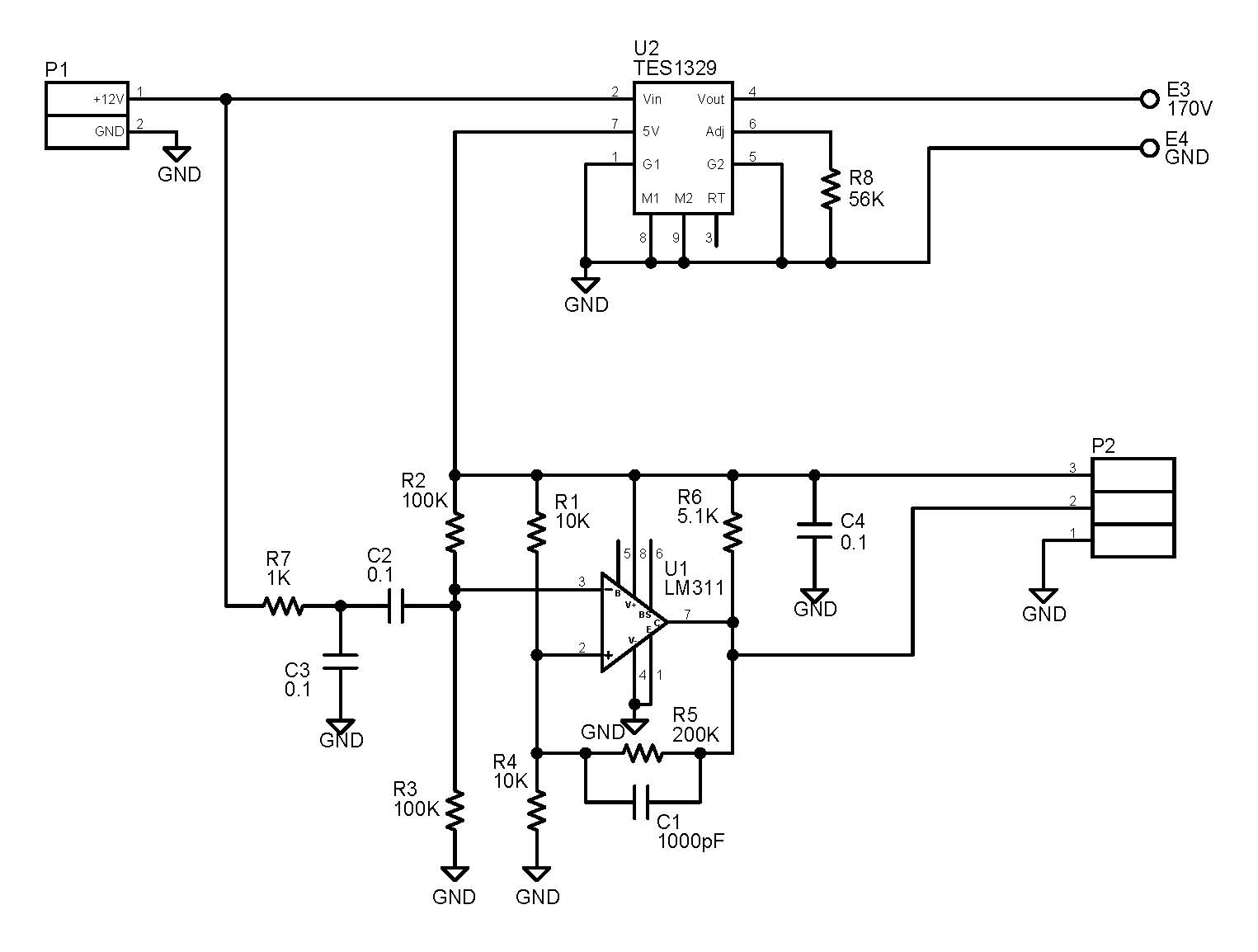
All the ICs were DIP style, all the resistors are rated 1/4W, and the nixie drivers were done the old-fashioned way with MPSA42 HV transistors. The IN-17 nixies only need roughly 130V to light up so it was not necessary to use a voltage doubler off the 120V mains; I used a simple half-wave DC power supply that rectifies the 120VAC mains to roughly 170VDC, and I used a 1uF 200V capacitor for the filtering.
The small size filter capacitor serves two purposes: so I could fit it on the packed space on the board and to provide less DC filtering so the nixies flicker slightly. As a result, the life of the nixies are longer because they are not lit continuously. A small neon bulb was inserted between the two pairs of IN-17 nixies as the colon indicator. 🔗 External reference
Related Circuits
This month's project is based on the 4017 chip that was used in a previous project. It is advisable to review the fundamentals of the 4017 chip as presented in last month's project. The circuit has been modified slightly;...
This circuit converts the ripple from a wall wart supply to a clean Line x 2 digital clock. Doing it this way eliminates the need to put AC into the unit, which then has to be rectified and filtered...
This precise one-pulse-per-second clock is constructed using a few common components and is powered by a 50 or 60 Hertz mains supply without any direct connection to it. A beep or metronome-like click, along with a visible flash, indicates...
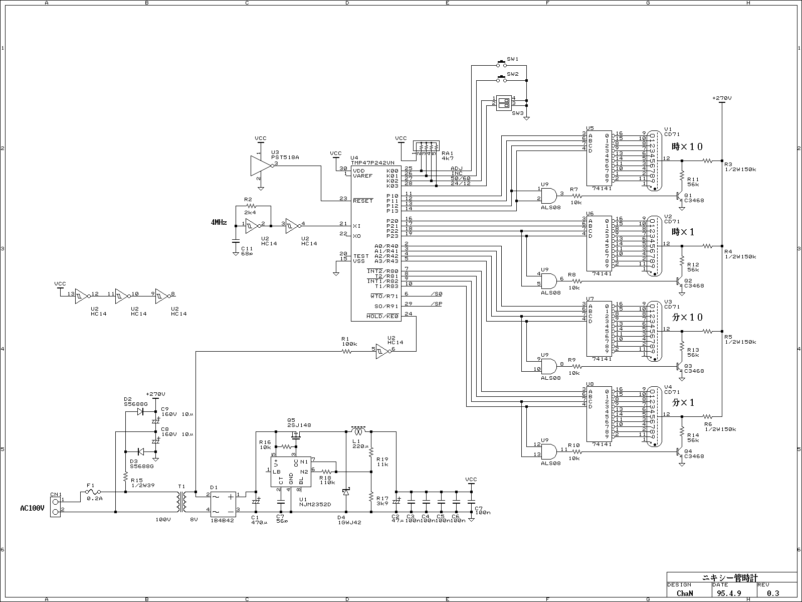
Because of the nixie-tube is a gas tube, it requires relatively high-voltage supply. Judging from archives, from 180 to 300 volts are used for supply voltage. In this project, 270 volts from rectified 100V line voltage directly is used....
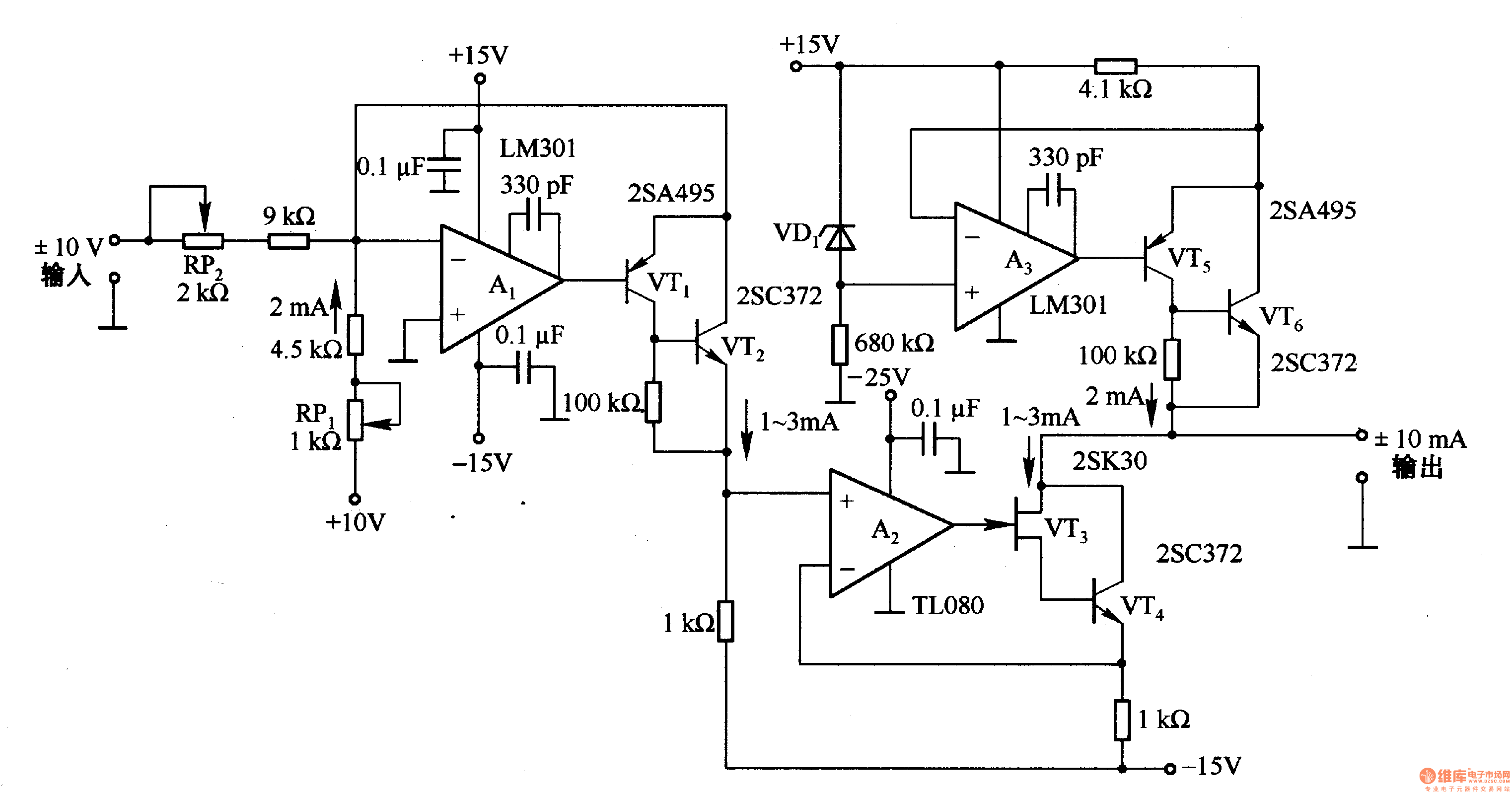
This circuit is designed for voltage-to-current conversion, specifically transforming a ±10V input voltage into a ±1mA output current. The conversion process is facilitated by operational amplifier A1 and transistors VT1 and VT2, which are responsible for altering the current...
An alternating display for a version 1 nixie clock inspired new logic designs for switching signals to the display. The design eliminated the 4013 flip-flop and two 4017 counters, leading to a redesign of the hours section and reset...