
Simple light-switch circuit
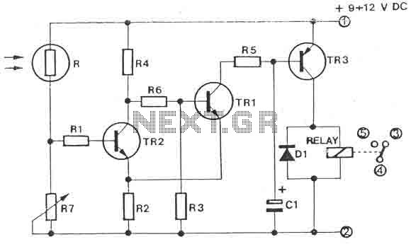
This circuit operates as a light-sensitive switch, making it ideal for applications such as automatic lighting systems, security lights, or garden lights that turn on at dusk. The core component of the circuit is the photoresistor, which changes its resistance based on the ambient light level. As light intensity decreases, the resistance of the photoresistor increases, affecting the voltage across it.
The voltage divider formed by the photoresistor and the trimmer (R7) is critical for setting the threshold at which the circuit activates. The trimmer allows for fine-tuning of sensitivity, enabling the user to adjust the light level required to trigger the switch. When the voltage across the photoresistor reaches a certain level, it provides enough base current to turn on transistor TR1.
Transistor TR1, being an NPN type, conducts when its base receives sufficient voltage, allowing current to flow from the collector to the emitter. This action turns on transistor TR2, which operates in a similar manner, amplifying the current to drive the relay. The relay, rated for 12V, serves as the output mechanism that can control larger loads, such as lights or other electrical devices, by switching them on or off based on the light conditions detected by the photoresistor.
The circuit also includes a diode (D1) connected in parallel with the relay to protect the transistors from back EMF generated when the relay coil is de-energized. Capacitor C1 acts as a filter capacitor, smoothing out any voltage fluctuations in the circuit, ensuring stable operation.
The combination of these components results in a reliable light-activated switch that can be adapted for various uses, providing a practical solution for automatic lighting control in different environments.The circuit is a light switch who triggers when light drops on photo resistor. It is fairly simple in construction and can be used in a million applications. The photoresistor and the trimmer work as a voltage divider and also polarize the transistor TR1. TR1 triggers TR2 and TR2 drives the relay. Trimmer R7 is for adjusting the sensitivity of the circuit. Parts: R = photoresistor R1= 4.7 Kohm R2= 1.2 Kohm R3= 2.2 Kohm R4= 1.2 Kohm R5= 1.2 Kohm R6= 2.7 Kohm R7= 100Kohm Trimmer C1 = 10uf/16V electrolytic TR1= BC107 - BC108 NPN TR2= BC107 - BC108 NPN TR3= BC557 - BC558 PNP - BC327 D1 = 1N4148 Relay = any 12Volt relay 🔗 External reference
Related Circuits

None of this triggering circuitry is exactly what is desired, but it will provide a starting point in the right direction. The triggering circuitry mentioned serves as a foundational element for various electronic applications, particularly in the realm of signal...
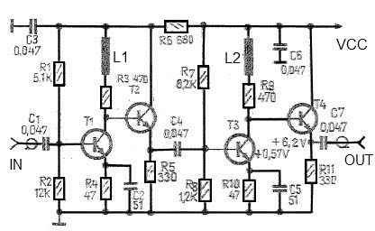
A simple and effective antenna amplifier can be built using the provided circuit diagram. This amplifier is designed for the frequency range of 35 kHz to 150 MHz. It utilizes transistors, offering a low non-linearity of 3 dB and...
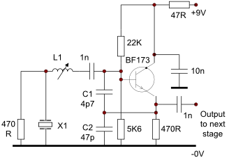
This circuit operates effectively from low frequencies up to at least 120 MHz using series resonant crystals in their fundamental or overtone mode. The output can be obtained from the feedback tap, a low impedance winding on L2, or...
Four simple 12V power supply circuits are designed to provide output voltages close to 12V. The first power supply circuit utilizes a BD139 transistor, a zener diode, and several passive components. Each schematic is straightforward to assemble and will...
The Reaction Capability Tester is utilized to assess and enhance an individual's quick-response abilities. It features various designs, with the depicted model comprising a CD4017 decimal counter and a light-emitting diode (LED). The construction of the Reaction Capability Tester...
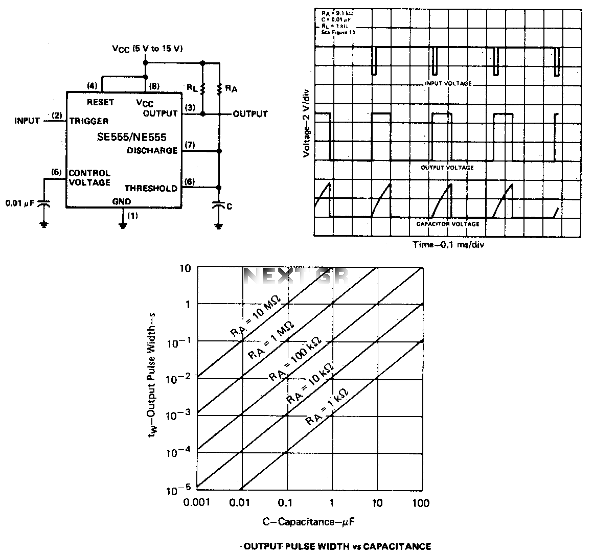
When the output is low, applying a negative-going pulse to the trigger input sets the flip-flop (Q goes low), driving the output high and turning off component 1. Capacitor C is then charged through resistor Ra until the voltage...