
Super lock circuit diagram
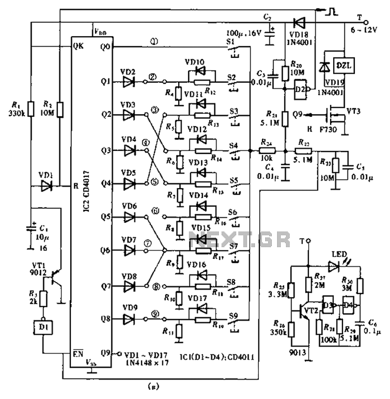
The circuit design features the CD4017 decade counter, which is capable of counting from 0 to 9, with each output terminal representing a specific count. In this application, the outputs are utilized to manage the locking mechanism based on the input of a specific password. When a valid password is entered through the input switching circuit, the corresponding output of the CD4017 is activated, allowing it to trigger a relay or another locking mechanism.
In terms of implementation, the circuit requires a power supply compatible with the operating voltage of the CD4017, typically between 3V to 15V. The password input switching circuit can be constructed using a matrix of push buttons, where each button corresponds to a digit in the password. The use of diodes in the matrix is critical to prevent ghosting and ensure that only the intended button press is registered.
The ancillary components may include resistors for pull-down configurations, capacitors for debouncing the switches, and possibly a microcontroller for additional functionality such as password management or logging attempts. The inclusion of a display, such as a 7-segment display, can provide visual feedback to the user, indicating whether the entered password is correct or incorrect.
Overall, this lock circuit design not only emphasizes security through a high number of password combinations but also maintains simplicity in its construction, making it suitable for various applications where enhanced security is required. As shown in the lock circuit by a decimal counter CD4017 composed by ten its output terminal is connected through a combination of the number of passwords the group consisting of up to 100 million group, can be called super-lock, which circuit is shown in shown. Circuit relatively simple, consisting of a CD4017 and 10 password input switching circuit related and ancillary components.
Related Circuits

This filter circuit, which utilizes the LM1458 or a similar operational amplifier, has a frequency response ranging from 300 Hz to 3.4 kHz, exhibiting a roll-off of 12 dB per octave outside the passband. Section A serves as the...
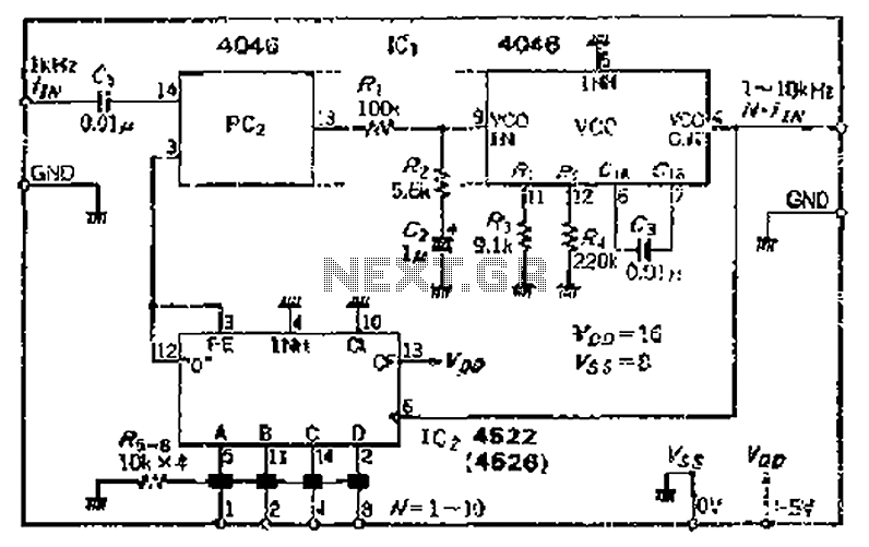
The CMOS IC 4046 Phase-Locked Loop (PLL) operates with a maximum frequency of 1 MHz. It is connected to a programmable divider, allowing it to process input frequencies. As the frequency increases by a factor of t, the circuit's...
The three circuits were based on the vacuum tube ECC83, designed to produce phono preamplifiers in compliance with RIAA standards. The described circuits utilize the ECC83 vacuum tube, a dual-triode component known for its low noise and high gain characteristics,...

The sound mixer circuit is designed for service applications. This mixer is straightforward to implement and cost-effective, as it consists of two transistors along with a few simple resistors and capacitors. The sound mixer circuit typically utilizes two transistors configured...
This circuit utilizes a sawtooth oscillator along with an output amplifier that drives a transistor. The components C1, C2, and L1 are essential for the oscillator's operation, forming a tank circuit that must be tuned to the resonant frequency....
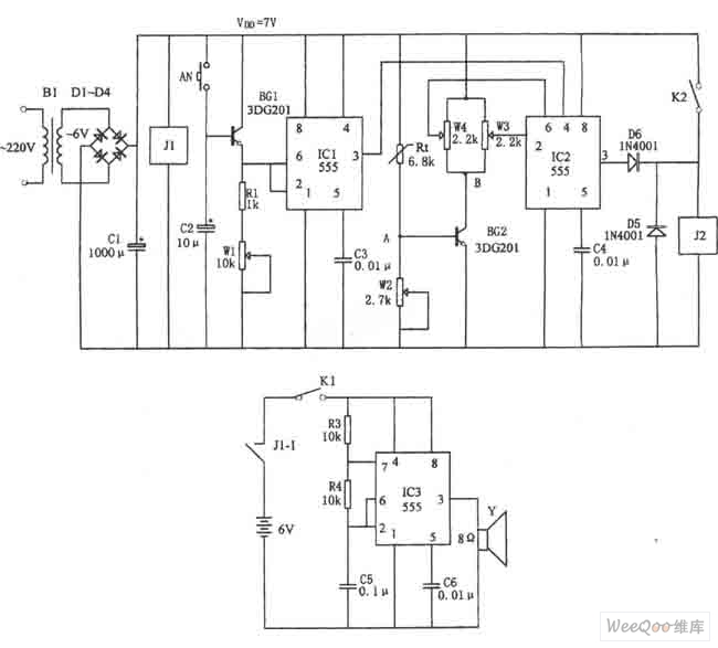
The figure illustrates the automatic watering control circuit for bean sprouts. The controller includes a step-down rectifier circuit, a power outage detection component (IC3), a timing control circuit (IC1), and a temperature control circuit (IC2). The step-down rectifier circuit...