
Sound mixer circuit

The sound mixer circuit typically utilizes two transistors configured in a way that allows for the mixing of audio signals from multiple sources. The transistors serve as amplifiers, boosting the audio signals to a suitable level for output. The circuit can be designed using common NPN or PNP transistors, depending on the desired characteristics of the mixer.
Resistors are employed to set the biasing conditions for the transistors, ensuring they operate within their active regions. The values of these resistors are crucial for controlling gain and impedance matching, which directly affects the quality and clarity of the mixed audio output. Capacitors are used for coupling and decoupling purposes, allowing AC signals to pass while blocking DC components, thereby preventing unwanted shifts in the signal level.
The overall layout of the circuit can be arranged on a printed circuit board (PCB) or a breadboard for prototyping. Attention should be given to the placement of components to minimize noise and interference, which can significantly impact audio quality. Proper grounding techniques and the use of shielded cables may also be considered to enhance performance.
This sound mixer circuit is suitable for various applications, including small audio mixing tasks in home studios, educational projects, or as a component in larger audio systems. Its simplicity and cost-effectiveness make it an ideal choice for beginners and hobbyists looking to explore audio electronics.Sound mixer circuit of Service This mixer is easy to implement and Expensive as it consists of 2 transistors And some simple resistors and capacito. 🔗 External reference
Related Circuits
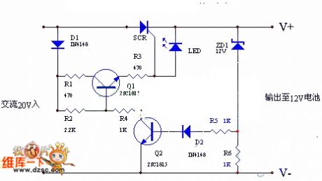
The circuit utilizes the positive half-cycle of an alternating current (AC) to charge a battery. It offers a rapid charging speed and has the potential to extend battery life. This charger is commonly used with standard motorcycles, demonstrating excellent...
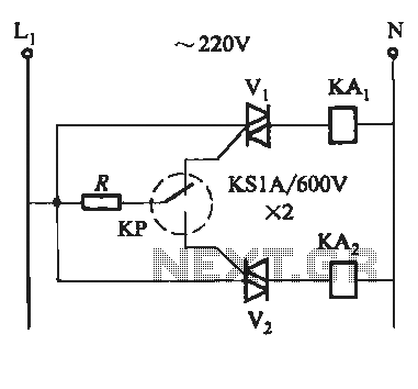
To prevent the failure of electric contact pressure thermometer contacts due to singeing, it is advisable to enhance the contacts, as illustrated in Fig. 11-60. Specifically, the output termination table for DC control utilizes two two-way thyristors or a...
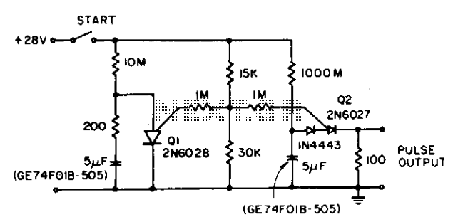
The circuit reduces the effective peak current of the output PUT, Q2. It allows the capacitor to charge with a high gate voltage and periodically lowers the gate voltage. When Q1 fires, the timing resistor can be set to...
It will operate on a single supply. It has been tested with a 9-volt battery and continues to perform well with a regulated 5-volt wall adapter. A modified version with input gains is available for connecting guitars or microphones,...
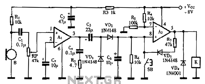
A practical voice-activated switch is presented. An A1 amplifier is connected to a conventional microphone (B) that picks up the audio control signal, which is then amplified. After amplification, the signal passes through components C5, VD1, and VD2, forming...
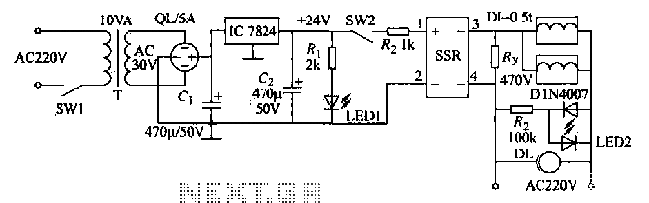
An AC solenoid-driven control circuit utilizing the SSR principle is illustrated. When switch SW1 is closed, a 220V AC transformer steps down the voltage to 30V AC through transformer T. The circuit includes a rectifier, capacitor C, and a...