
Selecting video op amps

The evolution of operational amplifiers (op-amps) has significantly advanced, transitioning from earlier models that required ±15V supplies and exhibited bandwidths of 50 MHz to contemporary devices that operate on ±5V supplies, achieving bandwidths of up to 1.4 GHz and slew rates reaching 6000V/µsec. This advancement presents a diverse range of op-amps tailored for various applications, particularly those demanding minimal supply voltage.
Key parameters must be considered when selecting an op-amp for specific applications. These include the nature of the signal being processed, the available supply voltages, and the power dissipation constraints of the application. Additionally, practical factors such as ease of implementation and compatibility with circuit board layouts play a crucial role in the selection process.
The composite-video format, which originated in the early 1940s, has been a significant standard in the op-amp industry, evolving to accommodate color signals by 1953. This format integrates white-level, color, and synchronization signals into a single conductor, where the synchronous signals initially guided the electron beam in cathode-ray tubes (CRTs) and now serve to time data streams in digital televisions. In the US composite video standard, synchronous pulses occur at a frequency of 15,734 Hz, with each pulse followed by a chroma burst composed of 3.58 MHz sine waves that establish a frequency reference for the embedded color information.
The composite-video receiver utilizes a chroma reference oscillator to resynchronize the bursts, with the subsequent video content following each burst. The maximum amplitudes for the synchronization signals, chroma, and white levels are 300 mV, 100 mV, and 707 mV, respectively, resulting in a peak-to-peak amplitude of approximately 1.05V. It is essential to note that not all chroma and white amplitude combinations are valid within the constraints of a specific video standard's color space.
Amplifiers must be appropriately biased within their supply limits to effectively handle the video signals. For instance, a digital-to-analog converter (DAC) output from a cable-tuner box typically maintains the synchronized signal at ground level, with video components extending positively. Although these DACs sample data at four times the chroma frequency, they may introduce artifacts necessitating filtering, often achieved through active filters employing op-amps. Some op-amps are designed with built-in filters to buffer DAC outputs when interfaced with standard 75-ohm video cables.
To mitigate reflections, the amplifier drives a reverse-termination resistor in series with the cable, which results in a loss of half the output amplitude. Consequently, the amplifier must have a gain of two to restore the standard output level. Furthermore, attention must be given to the voltage excursions of the signal concerning the available power supplies. While synchronous amplitudes can be accommodated by amplifiers with negative power supplies, such supplies may not always be present. Some op-amps are designed to operate linearly down to ground with rail-to-rail outputs; however, both MOS and bipolar rail-to-rail amplifiers exhibit non-linear behavior when approaching within 100 mV of the supply rails. This necessitates careful consideration in the design of circuits utilizing these components to ensure optimal performance and signal integrity.The first versions operated from ±15V supplies, featured bandwidths of 50 MHz, and delivered slew rates in the low hundreds of volts per microsecond. Today`s fastest amplifiers run on ±5V supplies with bandwidths of 1. 4 GHz and slew rates of 6000V/ µsec. There are hundreds of versions available, and, to add to the challenge, many applications require the
lowest possible supply voltage. To simplify the design choices, it`s important to identify major parameters of interest. Start with the kind of signal the op amp is passing, the available supply voltages, and the power dissipation that an application allows or tolerates. Important intangibles include ease of use and tolerance to board layout. This article covers the signal requirements and then reviews available amplifier topologies. Table 1 suggests amplifiers for different signals. The op-amp industry adopted the composite-video format in monochrome form in the early 1940s and the color standard in 1953 ( Figure 1 ).
White-level, color, and horizontal- and vertical-synchronous signals combine onto one conductor. The synchronous signals originally guided the electron beam`s horizontal line-scan in early CRTs. In today`s digital televisions they perform memory-mapped data-stream timing. In US composite video, the synchronous pulses repeat at a 15, 734-Hz rate. A flat region that represents a dark display and includes a chroma burst follows each horizontal synchronization. The burst is a number of 3. 58-MHz sine waves that serves as a frequency reference for subsequent embedded color information. The composite-video receiver has its own chroma reference oscillator that resynchronizes each burst. The video-line-picture content follows the chroma burst. Figure 1 shows a sample video content in which a steady color amplitude rides on a white level that increases across the line.
Pictures contain fairly unpredictable color and intensity content. The figure does not show the vertical-synchronization patterns, which are the same amplitude as the horizontal synchronization but of complex pattern and durations. The maximum amplitudes of the synchronization feature, the chroma, and the white part of the figure are 300, 100, and 707 mV, respectively.
These amplitudes make the maximum peak-to-peak standard composite-signal amplitude approximately 1. 05V p-p. Not all combinations of chroma and white amplitude exist in the color space of a particular video standard. The amplifier must be biased within its supplies to be able to handle the signal. One source of video might be a DAC output, such as a cable-tuner box. These sources generally place the bottom of the synchronized signal at ground, with video details going positive.
The boxes usually make output data samples at four times the chroma frequency but still have DAC-step artifacts that require filtering before use. Active filters using op amps frequently accomplish this task. Some op amps come with the appropriate filters and buffer the DAC output when you connect them to standard 75 © video cable.
The amplifier typically drives a reverse-termination resistor in series with the cable to absorb any reflections, and this step loses one-half the output amplitude. The amplifier then has a gain of two to recover standard-output amplitude. It also is important to consider the voltage excursions of the signal with respect to available power supplies.
The synchronous amplitude is on ground at the DAC output, and an amplifier has no problem passing this amplitude with a negative-power supply. However, negative supplies are often unavailable. Some amplifiers` inputs can linearly go to ground and have allegedly rail-to-rail outputs, but neither MOS nor bipolar rail-to-rail amplifiers are completely linear closer than about 100 mV from the supply rails.
Figure 2 shows the differential gain measurement of 🔗 External reference
Related Circuits
This device uses the second method, which requires about 100 times less parts, but adds motion detection to switch cameras. The usual way to detect motion is to store a complete video frame and then look for changes on...
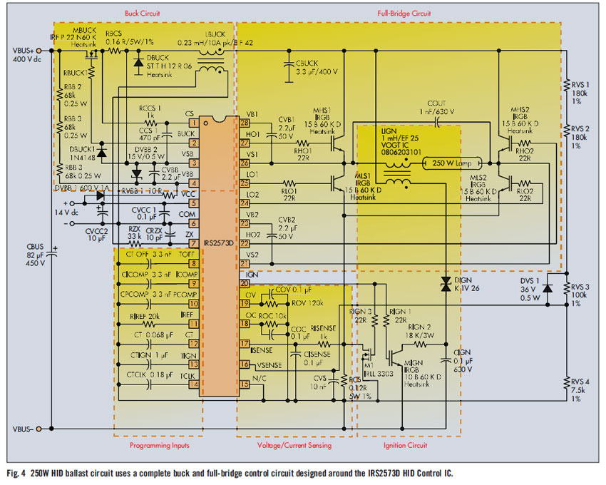
High brightness metal halide lamps typically have an efficacy of greater than 100 lumens per watt and a lifetime of 20,000 hours. High-intensity discharge (HID) lamps produce light using a technique similar to that used in fluorescent lamps, where...
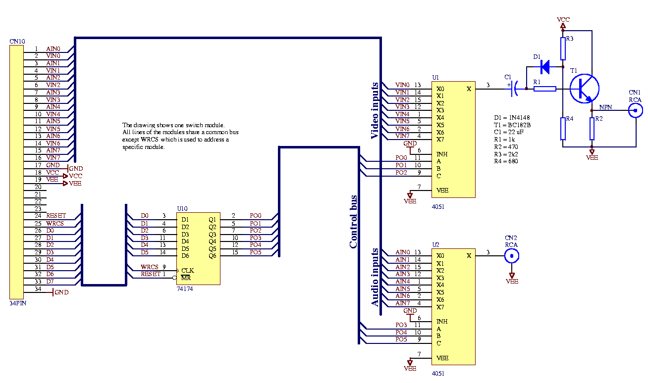
Each audio/video output can be switched to any of the eight inputs separately. One module drives one audio/video output and has a 34-pin connector to plug into the system interface. Video operational amplifiers (OPAs) can be used on the...
Circuit Overview Many families now own various electronic devices such as televisions, VCD players, video recorders, game consoles, cameras, and DVDs. This circuit involves an RF signal repeater designed to work with a television signal transmitter, covering a radius...
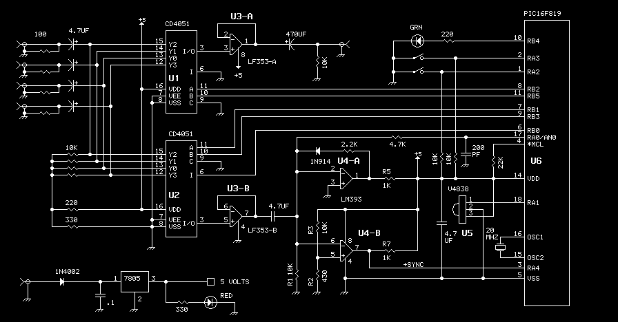
This is the original Circuit Cellar ImageWise Transmitter that was initially used. The code was disassembled to capture two half-size images, allowing for the extraction of images from both the odd and even fields. Code was then written to...
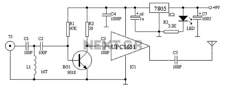
The project involves designing and constructing a wireless transmitter that operates on FM frequencies, enabling the transmission of video and audio signals over a specified distance to an FM tuner. This development addresses the growing demand for portability and...