
Video Switcher with PIC16F819
Three numeric sums (modulo 256) are computed from the 64 samples in the video frame. The first sum either adds or subtracts the video sample on a 'checkerboard' basis. Any object moving from one cell to an adjacent one will create a shift in the sum. A second sum is made using a different pattern. This sum is more sensitive to larger objects that may not affect the first sum. Likewise, a third sum is made using yet another pattern. Now we just add the 3 sums. A single 8-bit value now reacts to almost any changes in the visual field. All that needs to be done now is take the samples. There is no way for the PIC's A/D to sample 8 times on a single video scan line. However, it has no trouble taking one sample per line.
U4-A acts as a video clamp; it forces all of the sync tips to zero volts. This allows U4-B to slice off the sync pulses and feed them to the PIC. The PIC can now locate the Vertical Sync by looking for a set of 6 wide Horizontal Sync pulses. It then counts Horizontal Sync pulses to find the start of any particular video line.
The device operates on a motion detection principle that significantly reduces the complexity and memory requirements typically associated with video processing. By sampling only 64 specific locations on the video frame, the design minimizes the data load while still effectively detecting motion. The implementation of three distinct sums, calculated modulo 256, utilizes different sampling patterns to enhance sensitivity to varying object sizes and movements.
The first sum employs a checkerboard pattern, allowing for the detection of minor shifts in the sampled data corresponding to movement between adjacent cells. The second and third sums utilize alternative patterns designed to capture larger objects that may not influence the first sum, ensuring a comprehensive detection capability. The final output of these computations is condensed into a single 8-bit value, which provides a quick reference for any detected changes in the visual field.
The circuit utilizes operational amplifiers U4-A and U4-B to manage video signal processing. U4-A functions as a video clamp, stabilizing the sync tips to a zero-volt reference. This action enables U4-B to effectively extract the sync pulses from the video signal, which are essential for the PIC microcontroller's operation. The PIC then identifies the Vertical Sync signal by detecting a series of six wide Horizontal Sync pulses, allowing it to accurately count and time the Horizontal Sync pulses to determine the beginning of each video line.
This approach not only streamlines the design by reducing component count but also enhances the efficiency of motion detection in multi-camera setups, making it suitable for applications requiring real-time video analysis with minimal processing overhead.This device uses the second method (which, if you don't already know, requires about 100 times less parts), but adds motion detection to switch cameras. The usual way to detect motion is to store a complete video frame and then look for changes on successive frames.
Again, a lot of trouble can be saved by only sampling 64 locations on the screen at a low resolution (i.e. just using the A/D in the PIC). Since this device is designed for up to 4 cameras, that is still a lot of data to store in our PIC. Another method was developed to greatly reduce the memory requirements. Three numeric sums (modulo 256) are computed from the 64 samples in the video frame. The first sum either adds or subtracts the video sample on a 'checkerboard' basis (see fig-1). Any object moving from one cell to an adjacent one will create a shift in the sum. A second sum is made using the pattern in fig-2. This sum is more sensitive to larger objects that may not affect the first sum. Likewise, a third sum is made using the pattern in fig-3. Now we just add the 3 sums! A single 8-bit value now reacts to almost any changes in the visual field. All we need to do now is take the samples. There is no way for the PIC's A/D to sample 8 times on a single video scan line. However, it has no trouble taking one sample per line. U4-A acts as a 'video clamp': it forces all of the sync tips to zero volts. This allows U4-B to 'slice' off the sync pulses and feed them to the PIC. The PIC can now locate the Vertical Sync by looking for a set of 6 wide Horizontal Sync pulses. It then counts Horizontal Sync pulses to find the start of any particular video line. 🔗 External reference
Related Circuits
The VTG-01 is designed to display user defined text over a composite video signal. This is useful in a multitude of different applications such as adding titles to home movies and adding custom text to security videos. Text can...
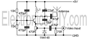
The circuit described is a simple audio/video transmitter with a range of 3 to 5 meters. The A/V signal source can be a VCR, satellite receiver, or video game console. A mixer that functions as an oscillator at the...
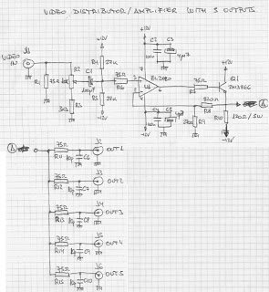
The circuit presented here has numerous applications. Essentially, the distribution amplifier receives a composite video signal from a video player (VCR) or a video generator (analog output) and buffers it, allowing it to be simultaneously sent to up to...
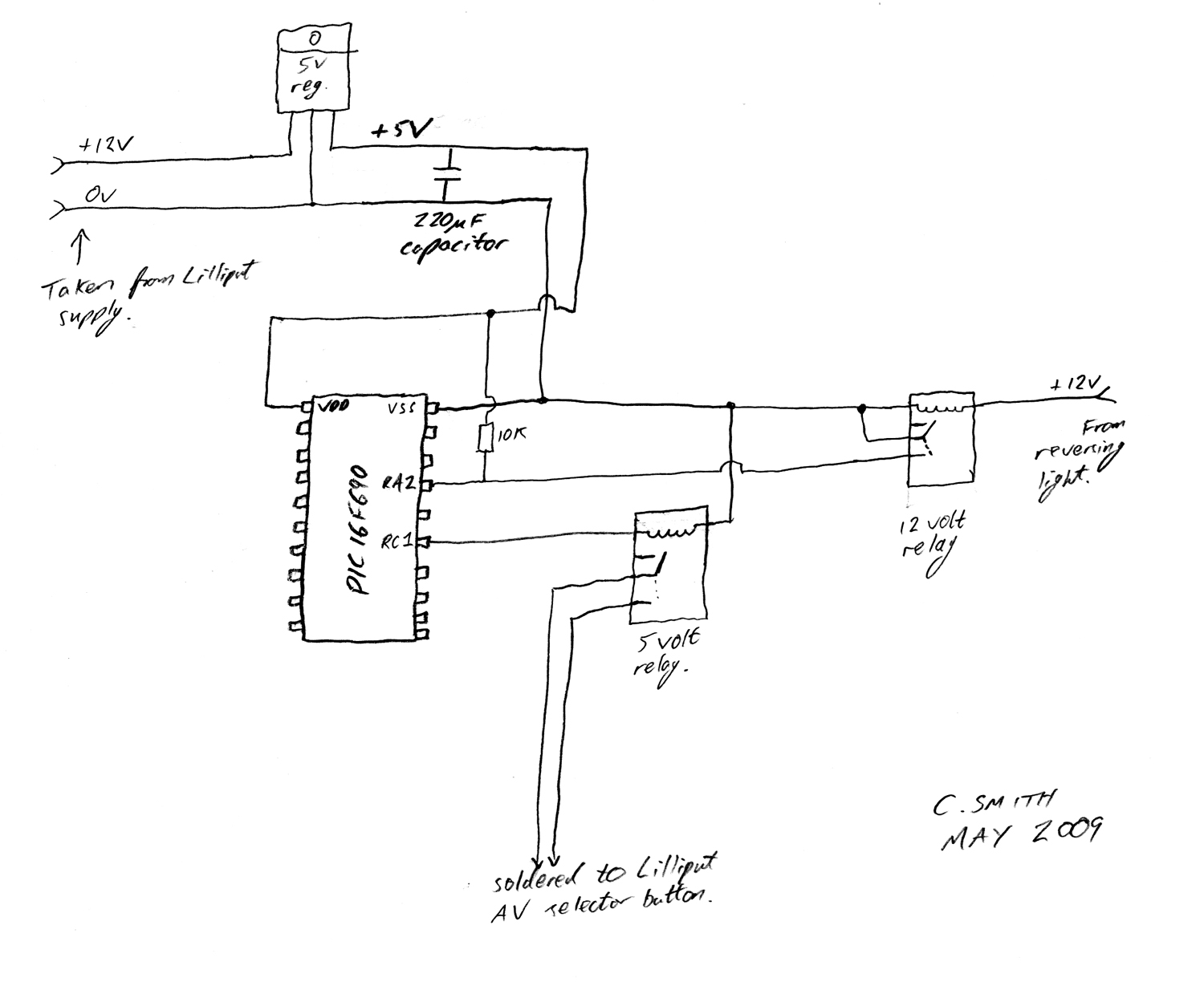
There have been numerous discussions regarding the Lilliput's inability to automatically switch, despite the presence of this feature in the secret menu. The Lilliput display is a versatile device often used in various applications, including professional video production and...
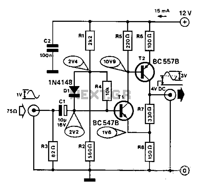
Commonly used for cameras or computers with black and white television connections, the amplifier has a gain of 3 and a bandwidth of 10 MHz. The described circuit is an amplifier designed for applications involving cameras or computers that interface...
The video transmissions from this unit can be received on a small portable, tunable, and battery-operated TV set, similar to those found in flea markets. The described unit is capable of transmitting video signals that can be captured by compact,...
Warning: include(partials/cookie-banner.php): Failed to open stream: Permission denied in /var/www/html/nextgr/view-circuit.php on line 713
Warning: include(): Failed opening 'partials/cookie-banner.php' for inclusion (include_path='.:/usr/share/php') in /var/www/html/nextgr/view-circuit.php on line 713