
Self Powered Current Sensing
A current sensing circuit serves a crucial role in monitoring the flow of electric current in various applications, particularly in high-side configurations. Such configurations are advantageous because they allow for the measurement of current without interrupting the circuit, thus maintaining the integrity of the load and ensuring accurate readings.
The high-side current sensing circuit typically consists of a shunt resistor placed between the load and the positive supply voltage. The voltage drop across this shunt resistor is proportional to the current flowing through it, following Ohm's Law (V = I * R). To accurately measure this voltage drop, an operational amplifier (op-amp) is often employed to amplify the small signal generated across the shunt resistor.
In a typical design, the op-amp is configured in a differential mode to reject common-mode voltage variations, which is essential in high-side applications where the supply voltage can be significantly higher than the ground reference. The output of the op-amp can then be fed into an analog-to-digital converter (ADC) for digital processing or directly utilized in a feedback loop for control applications.
To enhance the performance of the current sensing circuit, additional components such as filters may be included to minimize noise and improve stability. Moreover, proper selection of the shunt resistor value is critical; it must be low enough to minimize power loss while still providing a measurable voltage drop for accurate sensing.
In summary, the high-side current sensing circuit is an essential component in various electronic systems, providing reliable current measurements that are crucial for system monitoring, control, and protection.This is a current sensing circuit that senses the current at the high side (between load and positive supply). This circuit take advantage from.. 🔗 External reference
Related Circuits
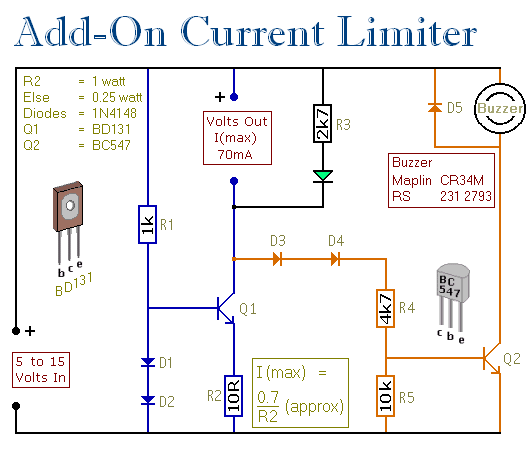
This circuit allows for setting a limit on the maximum output current from a power supply unit (PSU). It is particularly useful for initial project power-ups or during soak tests. By establishing an upper current limit, it protects both...
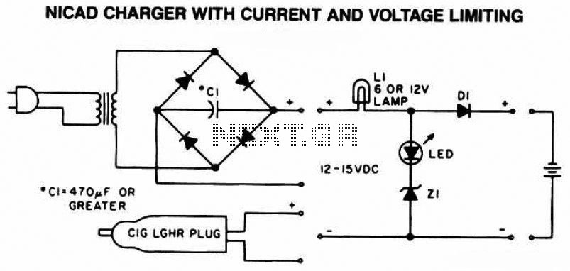
The following diagram is the schematic of a Ni-CAD battery charger circuit, which includes current and voltage limiting features to extend the battery's lifespan. The lamp L1 will illuminate brightly, and the LED will be off when the battery...
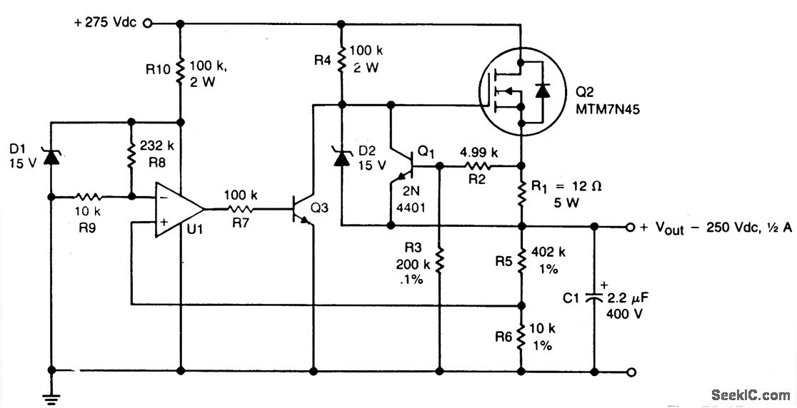
A TMOS MTM7N45 (Q2) functions as a series pass element in a linear high voltage supply that accepts +275 V unregulated input and produces a regulated output of 250 V, incorporating foldback current limiting. A 15 V zener diode,...
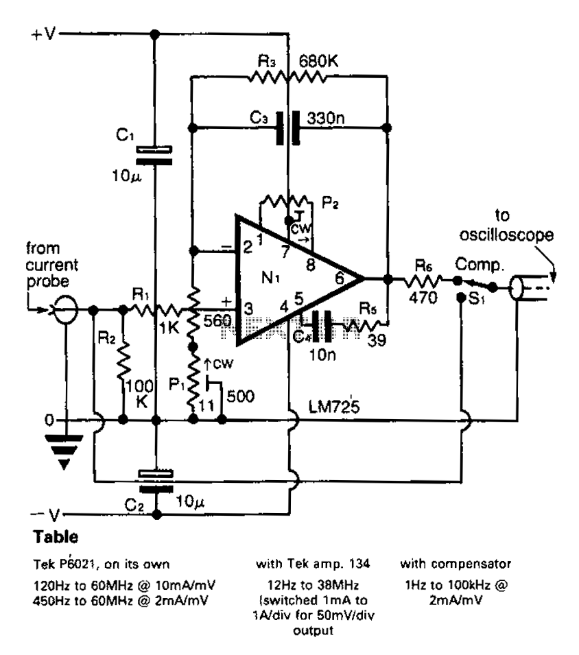
A clip-on current probe, like the Tektronix P6021, is a valuable tool for displaying current waveforms on an oscilloscope. However, it has limitations in low-frequency response. Specifically, the P6021 is sensitive to a range of 2mA/mV, and frequencies below...
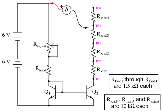
Two NPN transistors, specifically models 2N2222 or 2N3403, are recommended for this circuit. Larger "power" transistors may not behave similarly at low current levels. However, any pair of identical NPN transistors can be utilized to construct a current mirror....
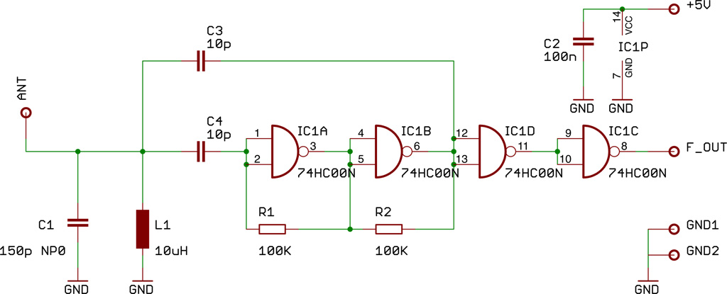
This document presents a compact Theremin module designed to connect to an Arduino board, which outputs sound to a speaker or generates control signals such as MIDI or servo commands. The device serves not only as a musical instrument...