
Self-powered Fast Battery-Tester
This battery testing circuit is designed to provide a straightforward and efficient means of assessing battery health across different voltage ranges. The dual-range functionality allows for flexibility in testing both standard 3V to 15V batteries and 1.5V cells, enhancing its usability in various applications. The use of FET Q1 as a constant current source ensures that the testing conditions remain stable, providing accurate readings regardless of the battery's initial voltage level. The inclusion of a square wave generator (IC1) and an inverter (IC2) enables effective voltage multiplication, ensuring that the circuit operates reliably even when testing lower voltage batteries.
The feedback mechanism involving Q3 and LED D7 offers a clear visual indication of the battery's condition, making it user-friendly. The gradual response of LED D7 to voltage fluctuations provides insight into the battery's performance under load, which is critical for determining its usability in practical applications. Additionally, the circuit's design allows for quick tests, minimizing the time required to assess battery health, which is particularly beneficial in environments where rapid diagnostics are essential.
Overall, this circuit represents an effective solution for battery testing, integrating essential components to deliver reliable performance while maintaining ease of use. Its design principles can be adapted for further enhancements or modifications, depending on specific testing requirements or battery types.This circuit runs a fast battery test without the need of power supply or expensive moving-coil voltmeters. It has two ranges: when SW1 is set as shown in the circuit diagram, the device can test 3V to 15V batteries.
When SW1 is switched to the other position, only 1. 5V cells can be tested. * Switch SW1 in the position opposite to that shown in th e circuit diagram. * Place the battery under test in a suitable holder or clip it to the circuit. * Wait some seconds in order to let C8 reach its full charge. * LED D1 illuminates very weakly only in presence of a new battery, otherwise is off. * Press P1 and keep an eye to LED D7. If D7 remains fully off the battery can be in very good state. * If D7 illuminates brightly for a few seconds, the battery is weak. * If D7 illuminates weakly for a few seconds, the battery is still good but is not new. * If you are suspecting a 1. 5V cell to be completely discharged, a better test can be made wiring two 1. 5V batteries in series, then running the 3V test. FET Q1 provides a constant current generator biasing LED D1 and Q2 Base. In this manner D1 illuminates at a constant intensity, independent of battery voltage from 3 to 15V and Q2 (when P1 is closed) applies a constant current load of about 120mA to the battery. IC1 is a square wave generator oscillating at about 3KHz. IC2 acts as an inverter and drives, together with IC1 but in anti-phase, Diodes D2-D6 and Capacitors C4-C7, obtaining a voltage multiplication.
C8 is charged by this raised voltage and R8-R10 form a voltage divider biasing the Base of Q3. When P1 is open, a very light load is applied to the battery under test and Q3 Base is biased in order to maintain LED D7 in the off state. Closing P1, a 120mA load is applied to the battery under test. If the battery is not fully charged, its output voltage starts reducing: when this voltage falls 0. 6V below the battery nominal voltage, Q3 Emitter becomes more negative than the Base, transistor is hard biased and D7 illuminates.
Obviously, this state of affairs lasts a few seconds: the time spent by C8 to reduce its initial voltage to the new one, proportional to the voltage of the loaded battery. If the battery under test is in a good charging state, its output voltage did not fall under a 120mA loading current, so LED D7 stays off.
When testing 1. 5V batteries, the circuit formed by Q1, Q2, D1, R1 & R2 doesn`t work well at this supply voltage, so a 150mA load current is applied to the BUT by means of the 10 Ohm resistor R3 after switching SW1A. Q3 bias is also changed via SW1B. 🔗 External reference
Related Circuits
The current source in the diagram reacts very quickly to changes in the input signal and may be utilized in specific measurements. Differential. The current source depicted in the schematic is designed to provide a stable output current that responds...
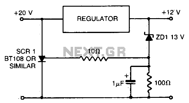
When using a regulated power supply to lower a supply voltage, there is always a risk that a failure in the power supply could result in a significant overvoltage condition across the load. To address overvoltage situations, the circuit...
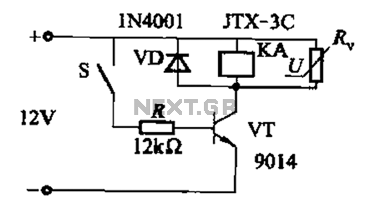
In a concrete circuit relay application, the transistor VT functions as a high-speed, high-voltage switch. The voltage requirement for switching is 5 to 10 times the rated voltage of the solenoid valve. The circuit is designed for a fast...

The issue with utilizing two Zener diodes in series for symmetrical clamping is that the knee of the Zener characteristics is imprecise. Additionally, charge storage within the Zeners can lead to speed issues, and the Zeners may exhibit slightly...
A schematic diagram of a fast pulse detector is shown in the figure below. An error detection rate of under 10% can be expected for a 60 ns pulse to achieve error-free operation. The fast pulse detector circuit is designed...
The image 3-6 depicts a thermistor temperature or frequency conversion circuit. The resistance of thermistors changes linearly with temperature, allowing this change to be utilized in a voltage-controlled oscillator. In the circuit, operational amplifiers A1-A4 are current-type LM3900 models,...
Warning: include(partials/cookie-banner.php): Failed to open stream: Permission denied in /var/www/html/nextgr/view-circuit.php on line 713
Warning: include(): Failed opening 'partials/cookie-banner.php' for inclusion (include_path='.:/usr/share/php') in /var/www/html/nextgr/view-circuit.php on line 713